
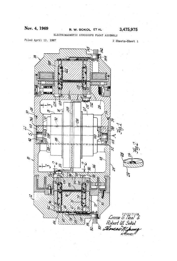
Electromagnetic Gyroscope Float Assembly (1969)
U.S. Patent No. 3,475,975, granted on November 4, 1969, to Robert W. Sokol and Lonnie G. Neal (assigned to General Motors Corporation), details an advanced float assembly architecture for single-axis floated gyroscopes used in precision inertial navigation systems.
Single-axis gyros in aerospace and guidance platforms require extreme precision and minimal mechanical restraint. Supporting the delicate internal float assembly on electromagnetic bearings and transmitting power via inductive transformer action avoids physical contact friction and wire torquing. However, previous designs required complex internal wiring, rigid conductive feedthrough rods, and numerous hermetic seals that introduced leakage paths and manufacturing difficulties. Sokol and Neal solved this by integrating bonded surface strip conductors and self-aligning spring contacts directly into modular float subassemblies, streamlining production while maintaining a hermetic barrier.
The Innovation: Modular Subassemblies and Surface Strip Circuitry
Earlier floated gyroscopes relied on rigid conductive metal rods driven through the float shell walls to route power to the internal drive motors. Each penetration required delicate glass-to-metal or ceramic hermetic seals to prevent flotation fluid from leaking inside.
Sokol and Neal eliminated internal wiring harnesses and rigid feedthrough rods by integrating planar conductive pathways directly onto the interior surfaces of the float shell.
Key Mechanical Advantages
- Reduction of Hermetic Penetrations: Power passes into each float half through a single sealed end-wall pin, eliminating multi-point rod penetrations through the cylindrical casing.
- Modular Subassembly Architecture: The stator pole pieces, windings, motor cartridge, and housing shells can be tested and preassembled independently before final mating.
- Solderless Blind-Mating Connections: Bringing the modular halves together automatically establishes the circuit connections using resilient spring leaves that press against bonded arcuate conductor tracks.
The Core Design: The Modular Float System
The gyroscope achieves complete non-contact magnetic suspension and two-phase power induction across symmetrical axial assemblies:
- Two-Piece Float Shell (24, 26)
- Left Float Half (24): A cylindrical cup with a stepped interior bore that carries an insulatively bonded axial conductor strip (114) branching into an arcuate distribution track (116).
- Right Float Half (26): A matching cylindrical cup equipped with integral pillow blocks (36, 38) that securely seat the motor/rotor cartridge (16, 18, 20). It carries an independent bonded conductor strip (134) and arcuate track (136).
- Mating Interface: The two halves slide together coaxially, seating against an annular shoulder (34) and sealing tightly with an O-ring (54).
- Inductive Suspension and Power Transfer Pole Pieces (70, 96 and 120, 126)
- Primary Stator Assemblies (70, 120): Ferrite pole pieces housed in the outer end housings (12, 14), each containing an annular slot holding an inductive primary winding (74, 122).
- Secondary Float Pickups (96, 126): Ferrite pole pieces seated in external cavities on the float end walls (46, 28), each holding a secondary winding (98, 128).
- Dual-Function Field: Energizing the primary coils generates alternating flux across the axial working gaps. This flux creates axial centering forces, while concentric annular surface grooves in pole tips (80, 106) produce flux concentrations that resist radial displacement. Simultaneously, transformer action induces two distinct electrical phases into secondary coils (98, 128).
How the Apparatus Functions
Assembly follows an efficient, multi-stage progression designed for high-precision manufacturing:
| Step | Action | Functional Purpose |
| 1. Cartridge Seating | The preassembled rotor (16) and dual hysteresis motors (18, 20) are bolted into pillow blocks (36, 38) of float portion (26). | Resilient spring fingers (138, 140) automatically compress against track (136), instantly completing the Phase 2 power circuit. |
| 2. Coaxial Shell Closure | Left float shell (24) is slid over right shell (26) until lip (50) seats against shoulder (34). | Resilient contacts (118) from the motors engage arcuate track (116), completing the Phase 1 circuit without manual wiring or soldering. |
| 3. Transformer Insertion | Slotted ferrite pole assemblies (96, 126) are inserted into outer float cavities (90, 124). | Spring leaves (102, 130) contact center feedthrough pins (110, 131), while ground contacts (103, 129) ground the coils to the metal float body. |
| 4. Magnetic Alignment | Float assembly (10) is centered between gyro end housings (12, 14) carrying primary pole pieces (70, 120). | Energizing the primary windings establishes magnetic suspension and induces power into both motors across the fluid-filled gap. |
Technical Components
| Component | Function |
| Float Shell Halves (24, 26) | Mutually engageable cylindrical cups forming a sealed housing for the inertial sensing rotor and motors. |
| Pillow Blocks (36, 38) & Clamps (42, 44) | Precision mounting saddles in float half (26) that support the rotor shaft (40). |
| Ferrite Pole Pieces (70, 96, 120, 126) | Low-loss magnetic cores with annular slots housing inductive coils. |
| Concentric Grooved Pole Tips (80, 106) | Machined disk faces with concentric circular lands that concentrate magnetic flux to generate radial centering forces. |
| Bonded Strip Conductors (114, 134) & Tracks (116, 136) | Thin, insulatively bonded copper ribbons running along interior float walls to route power directly to motor terminals. |
| Resilient Spring Contacts (78, 102, 118, 138) | Flexible spring fingers providing solderless, vibration-resistant electrical contacts upon mechanical assembly. |
| Feedthrough Plugs (112, 132) & Pins (110, 131) | Hermetically sealed single-point center terminals passing electrical current through float end walls without fluid leakage. |
Historical and Technical Impact
The design developed by Robert W. Sokol and Lonnie G. Neal represented an important refinement in the engineering of high-precision inertial guidance instruments:
- Enhanced Reliability and Hermeticity: Replacing multiple rigid conductive feedthrough rods with bonded interior foil traces and a single central terminal reduced the risk of flotation fluid leaking into the rotor chamber.
- Production Efficiency: The modular, plug-and-socket subassembly technique eliminated labor-intensive hand-soldering of fine leads within tight cavity enclosures, allowing repeatable mass production of navigation-grade gyroscopes.
- Torque-Free Operation: Delivering two-phase excitation entirely via electromagnetic induction eliminated the parasitic restraint torques that flexible physical lead wires exert on sensitive gyro floats.
About the Inventors
- Lonnie G. Neal: An African American engineer and inventor who contributed to aerospace and electromechanical design at General Motors’ AC Electronics Division in Milwaukee, Wisconsin. AC Electronics was a premier contractor for inertial guidance systems during the Apollo space program and advanced defense navigation initiatives.
- Robert W. Sokol: Co-inventor and systems engineer at General Motors, collaborating on precision electro-mechanical instrumentation, magnetic bearings, and navigational hardware.
Summary of Claims
The patent explicitly claims:
- A gyro float assembly formed of two mutually engageable cylindrical cup sections sharing a common longitudinal axis, each carrying an insulatively bonded conductor strip along its interior wall.
- Mounting structure where seating the motor cartridge into the float automatically connects resilient motor contacts to a bonded conductor track, and closing the two float halves completes the second motor circuit.
- End-wall transformer subassemblies featuring slotted ferrite pole pieces, inductive coils, and resilient contact springs that transfer distinct electrical phases into the float by transformer action.
- Pole tips provided with matching concentric grooves that concentrate magnetic flux across the axial gap to supply radial centering forces for magnetic float suspension.
