
Electrical Railway System (1897)
U.S. Patent No. 588,176, granted on August 17, 1897, to William B. Purvis, addresses a fundamental safety and infrastructure challenge in late 19th-century urban transit: safely delivering high-voltage electric power to streetcars without exposing pedestrians and horses to live overhead wires or continuously electrified surface rails.
Early electric streetcars relied heavily on overhead trolley wires, which were prone to snapping and cluttering city skylines, or open third rails that posed lethal electrocution hazards at street level. Purvis, an inventor residing in Philadelphia, Pennsylvania, developed an enclosed underground conduit system that energized surface contact points only at the exact instant a trolley car passed over them, instantly de-energizing the circuit once the car cleared the contact point.
The Innovation: The Closed Conduit and Resilient Switch System
The core principle of the Purvis system is a mechanical “power-on-demand” switching mechanism housed inside an open-bottom, moisture-draining underground conduit. The system completely insulates the primary high-voltage feeder wire until the mechanical weight and depression of a passing car physically closes the circuit.
- The Underground Conduit and Insulated Feeder (F, H, J)
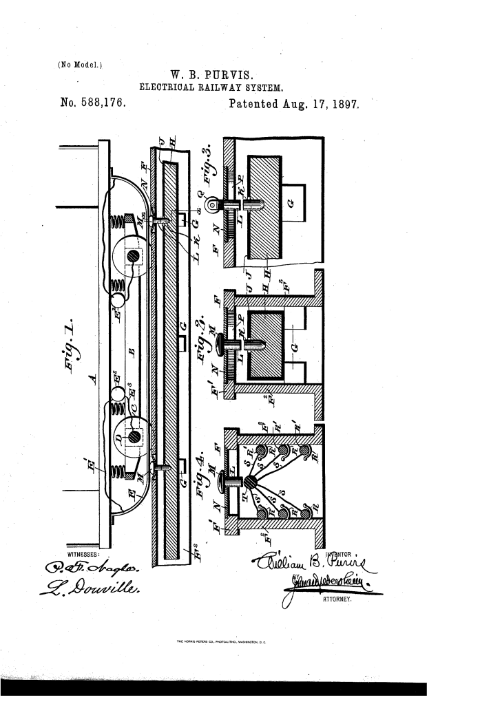
- The foundation of the system is a specialized track conduit (F) featuring a protective top (F1) and depending side walls (F2).
- The bottom of the conduit remains open to the ground, allowing water, dirt, and moisture to freely drain away from the electrical components.
- Inside the conduit, a series of interior lugs (G) support and insulate the main high-voltage electrical conductor or feeder wire (H), protected by durable insulation (J).
- The Resilient Diaphragm and Plunger Pin (L, N)
- Positioned along the track at intervals shorter than the length of a streetcar are movable contact pins (L).
- Each pin is suspended in an elastic, resilient diaphragm (N). When at rest, the diaphragm holds the pin elevated and physically separated from the live electrical contact (K), keeping the surface safe and dead.
- The contact pin can be fitted with either a stationary rounded head (M) or a friction-reducing rolling wheel (Q) to engage the vehicle smoothly.
- The Vehicle Contact Strip and Circuit Return (E, E1, E2, E3)
- Mounted beneath the car body (A) and trucks (B) is a long, flexible, yielding metal contact strip (E), fully insulated from the car frame.
- As the car rolls forward, strip (E) presses down on the succession of contact pins (L), forcing them against the internal feeder contacts to complete the circuit.
- Current travels through conductor (E1) to drive the car motor (E2), before grounding safely through return conductor (E3) and the wheel axle (D).
How the System Functions
The operational cycle relies on precise mechanical spacing and natural elasticity to ensure uninterrupted power delivery without continuous electrification:
| Step | Action | Operational Purpose |
| 1. Approach | The car (A) moves along the track; the flexible strip (E) engages the pin head (M) or roller (Q). | Initiates mechanical contact before the previous power point is fully cleared. |
| 2. Depression | The downward tension of strip (E) flexes diaphragm (N), pushing pin (L) into contact with stationary contact (K) or feeder (T). | Closes the local electrical circuit and energizes only that specific point in the track. |
| 3. Power Delivery | Electricity flows from feeder (H) through pin (L) and strip (E) to the motor (E2). | Supplies continuous propulsion current to the streetcar while keeping surrounding street surface dead. |
| 4. Disengagement | The car advances past the pin; the flexible strip (E) clears the contact head. | Relieves downward mechanical pressure on the assembly. |
| 5. Circuit Break | The resilient diaphragm (N) instantly rebounds, lifting pin (L) away from the live feeder. | Immediately breaks the electrical connection, neutralizing the surface point before pedestrians can step on it. |
Key Technical Components
- Car Assembly (A, B, C, D): Standard streetcar trucks, wheels, and axles configured to complete the electrical ground return path.
- Under-Car Contact Strip (E): A long, spring-tempered metal strip adjusted to span multiple contact points simultaneously, ensuring seamless current transfer without power stutter.
- Conduit Housing (F, F1, F2): Protective underground duct work with an open floor designed to eliminate dangerous water accumulation around high-voltage feeds.
- Auxiliary Feeder Array (R, T): An alternate configuration (Figure 4) employing multiple auxiliary feed wires (R) linked to a central conductor rail (T) to distribute heavy industrial electrical loads efficiently.
- Rolling Contact (Q): A rotatable wheel mounted atop the plunger pin (Figure 3) engineered to minimize physical wear and frictional drag against the passing car strip.
Historical and Industrial Significance
William B. Purvis’s electrical railway system represented an important evolutionary step in late 19th-century municipal transit design:
- Elimination of Overhead Hazards: By bringing power underground without creating a constantly live open rail, it offered a viable solution to the bird’s-nest tangle of high-voltage overhead wires that plagued major cities like New York and Philadelphia during the blizzard of 1888.
- Urban Safety: Pedestrians, draft horses, and cross-traffic could traverse the tracks safely without danger of shock, as surface pins remained entirely inert until fully covered by a passing transit car.
- Self-Draining Durability: The open-bottom conduit design directly addressed one of the biggest engineering failures of early underground electrical conduits—short-circuiting caused by trapped rainwater, snowmelt, and street sludge.
About the Inventor: William B. Purvis
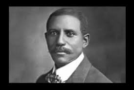
William B. Purvis (1838–1914) was a prolific African American inventor and entrepreneur based in Philadelphia, Pennsylvania.
- Prolific Output: Purvis secured over a dozen U.S. patents across multiple technical disciplines, including automated paper bag machinery, fountain pens, magnetic edge-aligning devices, and hand-operated stamps.
- Transit Innovation: His deep interest in transportation mechanics resulted in multiple patents related to rail safety, electrical distribution, and track switches throughout the 1880s and 1890s.
- Commercial Acumen: Unlike many independent inventors of his era who struggled to commercialize their ideas, Purvis successfully assigned and licensed several of his high-speed manufacturing and transit inventions to commercial firms, cementing his legacy as one of the Gilded Age’s most versatile industrial minds.
Summary of Claims
The patent explicitly claims:
- An electric railway conduit featuring an open bottom for moisture drainage and interior insulating supports carrying a primary electrical conductor.
- A series of vertically movable contact pins supported by resilient, self-restoring diaphragms that hold the contacts out of engagement when at rest.
- An under-car yielding contact strip arranged to depress consecutive contact pins into connection with the internal feeder as the car advances, automatically breaking the circuit when the car passes.
