

Electric Railway Trolley (1893)
U.S. Patent No. 505,370, granted on September 19, 1893, to Elbert R. Robinson, describes an advanced overhead trolley system for electric streetcars. Elbert Robinson, an inventive mechanical mind based in Nashville, Tennessee, designed a multi-wheeled contact wheel and specialized vehicle guides to prevent streetcars from losing power or experiencing dangerous line disruptions.
This specific invention solved a persistent problem in early electrical transit: how to keep the trolley wheel securely connected to the overhead power wire when a streetcar went around sharp curves, traveled down steep inclines, or hit uneven patches of track.
The Innovation: The “Three-Pulley Self-Guiding Wheel”
Traditional trolley poles used a single, deeply grooved wheel to grip the live wire. If the car turned sharply or vibrated violently, the wire would jump out of the groove, cutting the electricity and sparking dangerously. Robinson’s breakthrough was dividing the contact mechanism into three independent pulleys running on a single axle.
By separating the wheels and shaping the outer pulleys with wide, inwardly sloped surfaces, Robinson ensured that even if the line slipped out of the center track, the movement of the car would automatically guide the wire right back into place.
Why This Design Works
- Independent Rotation: The center wheel can spin at a different speed than the outer wheels, drastically reducing friction, binding, and mechanical wear on the copper wire.
- Automatic Recentering: The outer pulleys feature broad, inwardly inclined treads (7) that use gravity and line tension to slide an errant wire directly back into the primary groove.
- Continuous Power Contact: If the car swerves or tilts, the wide, flared outer flanges (6) catch the wire rather than letting it throw the trolley arm off the line entirely.
- Integrated Lubrication: Internal oil grooves (8) within the axle constantly distribute grease through perforated channels to keep the high-speed pulleys spinning smoothly without freezing up.
Key Technical Components
The system consists of a dynamic trolley wheel head working in tandem with safety guides mounted on the roof of the streetcar:
| Component | Function |
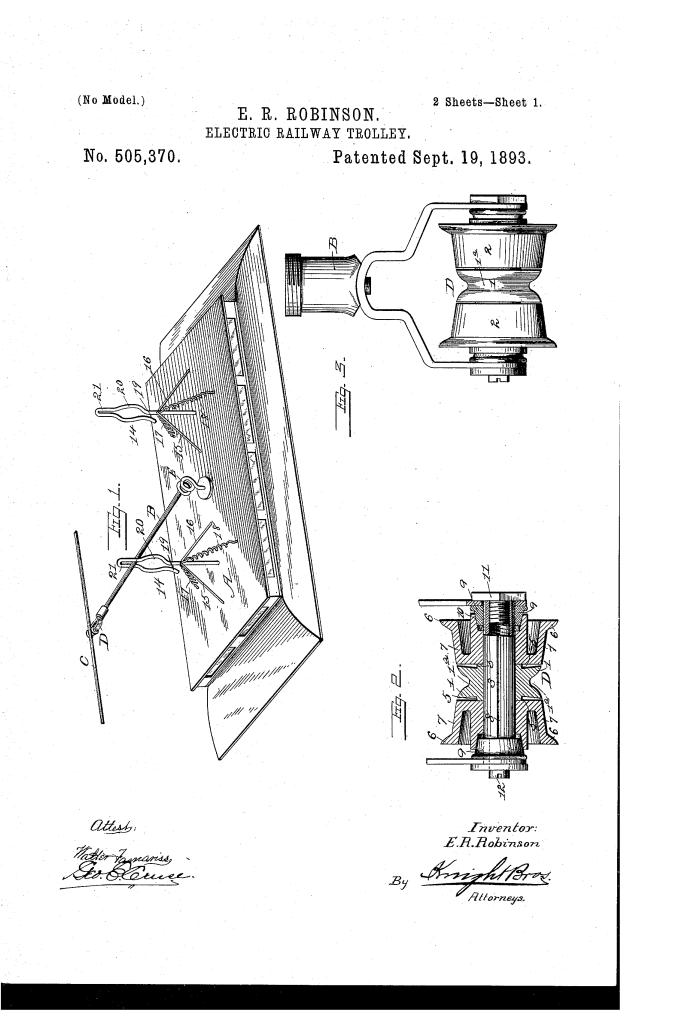
| Middle Pulley (1) | The core contact wheel, featuring a sharp central groove (1) to cradle the overhead electric wire (C) during normal straight line travel. |
| Outer Pulleys (2) | Two dished, flanking wheels with broad, inclined treads (7) and turned-out flanges (6) designed to catch loose wires. |
| Oil Grooves & Thimbles (8, 9) | Internal channels carved into the main axle (3) that hold and regulate the flow of lubricant across the independent hubs. |
| Roof Turn-Table | A rotating base mounted in the middle of the car roof (A) that allows the main trolley arm (B) to swivel laterally. |
| Open Metal Guides (14) | Twin loop-style metal frames secured to both ends of the car roof to capture, steady, and restrict the trolley arm’s movement. |
How the Apparatus Functions
The device relies on mechanical geometry and spring tension to maintain a constant electrical circuit under harsh transit conditions:
| Step | Action | Operational Purpose |
| 1. Normal Running | The heavy elevating spring (E) pushes the trolley arm upward, planting the live wire securely into the central grooved pulley (1). | Conducts steady electrical current to the car motor while running smoothly on flat, straight tracks. |
| 2. Cornering Displacement | As the car rounds a curve, the wire naturally slides out of the center groove and drops onto an outer pulley (2). | Prevents an immediate derailment of the connection; the wide tread keeps drawing power from the line. |
| 3. Self-Correction | The inward incline (7) of the outer pulley forces the wire to slide back down into the primary center groove. | Minimizes structural wear on the main contact pulley and keeps the system automatically aligned without human intervention. |
| 4. Structural Guarding | When hitting severe track bumps, the trolley arm enters the contracted loop (21) of the roof-mounted metal guide. | Absorbs the shock, controls the bounce, and stops the trolley pole from violently snapping away from the overhead wires. |
Historical and Scientific Impact
Elbert R. Robinson’s invention arrived during the critical foundational years of American urban electric rail networks, providing vital improvements to early mass transit:
“The object in so forming these outside pulleys is to cause the wire when thrown on either of them, to be guided back into the groove of the middle pulley thus saving the wear…”
- Infrastructure Longevity: By reducing the need for aggressive, ultra-deep grooves on a single wheel, Robinson’s design saved cities thousands of dollars in premature wire replacement costs.
- Enhanced Safety: Preventing the trolley pole from popping off stopped the heavy metal arms from swinging wildly into the street or snapping overhead lines down onto pedestrians.
- Curve Mitigation: The specialized “bulge” (20) in the roof guides allowed intentional lateral play, meaning municipal engineers could design tighter turns in crowded city layouts where wires were deliberately hung lower.
About the Inventor: Elbert R. Robinson
Elbert R. Robinson was a prolific late 19th-century African American inventor whose work focused heavily on improving the rapidly expanding railway and streetcar infrastructure of the era.
- Patents: In addition to his electric trolley improvements, Robinson secured significant patents for casting composite railway wheels (1897) and creating highly durable molded vehicle wheels designed to withstand heavy industrial stress.
- Legal and Business Battles: Operating during the challenging Post-Reconstruction era, Robinson frequently fought high-profile legal battles against major transit corporations to protect his intellectual property rights and enforce his patent claims.
- Legacy: Robinson’s designs helped lay the groundwork for more reliable, heavy-duty electrical contact systems, pushing urban streetcar design past its experimental phases into a highly functional era of mass public transportation.
Summary of Claims
The patent explicitly claims:
- A trolley wheel constructed with a centrally grooved tread flanked by broad, supplementary flanged treads to capture wires when the axle shifts out of a right angle.
- The mechanical combination of a framed axle with internal oil grooves and three independent pulleys featuring inwardly inclined treads.
- A hollowed middle pulley design utilizing integrated, perforated trunnions to actively feed lubricant directly to the spin surfaces of the outer dished wheels.
- The inclusion of roof-mounted, open metal loop guides backed by stabilizing springs to provide a flexible, shock-absorbing path for the trolley arm.
