

Electric-Railway Trolley (Elbert R. Robinson, No. 505,370)
The patent by Elbert R. Robinson of Nashville, Tennessee, describes several novel improvements for the electric trolley system used in overhead electric railways. The main goal was to prevent the trolley from jumping the wire (dewiring), especially when rounding curves or going over uneven track.
Invention and Mechanism
The invention focuses on improvements to the trolley wheel, the trolley guides, and the overall trolley mounting system.
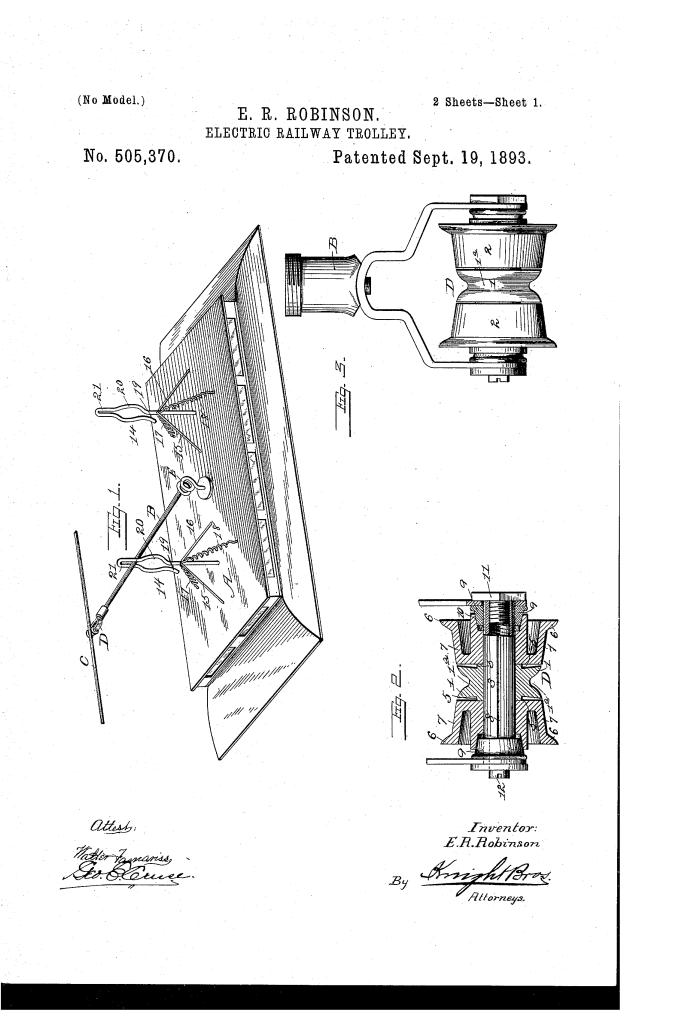
1. Improved Trolley Wheel (D)
The wheel is a compound structure mounted on a single axle (3) and consists of three independent pulleys:
- Central Grooved Pulley (1): This pulley has a groove (1′) that directly contacts the overhead wire (C). It revolves independently.
- Two Outer Beveled Pulleys (2): These side pulleys have outwardly turned flanges (6) and treads (7) that incline inwardly toward the groove of the central pulley.
- Function: If the car rounds a curve and the wire is momentarily thrown onto one of the outside pulleys, the inward incline of the tread (7) automatically guides the wire back into the central groove, preventing the trolley from slipping off the wire. The pulleys revolve independently, reducing wear and friction.
- Lubrication: The axle (3) has grooves (8) to distribute oil supplied from the ends, where thimbles (9) confine the oil and also serve as bearings for the outside pulleys.
2. Trolley Guides (I and K)
Two guides are mounted on the car top (A), one at each end.
- Structure: The guide is an open metal loop secured by braces (15, 16) and held with a yielding force by springs (17, 18).
- Contour: The loop has three main sections:
- Opening (19): Near the bottom to receive the trolley arm (B).
- Bulge/Enlarged Portion (20): Above the opening, designed to permit lateral play when the car is rounding a curve. This allows the trolley arm to momentarily track off-center.
- Contracted Loop (21): The narrowest top section, designed to guide the trolley back beneath the wire and prevent it from bounding off when the car goes over bumps.
- Function: The guides work together to catch the trolley arm if it swings too far laterally or bounces vertically, always nudging it back toward the central vertical plane of the wire.
3. Mounting System
- The trolley arm (B) is mounted on a turn-table in the middle of the car, allowing it to pivot horizontally.
- An elevating spring (E) is provided to hold the trolley wheel (D) against the overhead wire (C).
Historical Significance and the Inventor
The patent by Elbert R. Robinson in 1893 comes at a critical time in the history of electric street railways (trolley systems), which were rapidly replacing horse-drawn and cable cars across American cities.
- The Problem of Dewiring: In the early 1890s, one of the biggest operational flaws of overhead trolley systems was the frequent dewiring (the trolley wheel jumping off the wire). This halted service, required manual reattachment by the motorman, and was a major source of delays and frustration.
- Innovation in Trolley Heads: Robinson’s complex, three-pulley wheel design (a “trolley wheel” with “lateral guide pulleys”) was an attempt to solve this problem mechanically. By using an inclined/beveled surface to self-center the wire, he sought to reduce the need for constant, perfect alignment.
- The Guide System: The use of spring-loaded guides on the car itself was an additional safety layer, showing an integrated, multi-part approach to system reliability. This demonstrated that simple mechanical solutions were still favored for robust, high-stress components before reliable electrical control systems became commonplace.
Relation to Current Items
Robinson’s invention addresses issues of alignment and containment that are still central to modern transportation and power transfer systems:
- Pantographs and Tractive Current Collection: While the trolley pole with a wheel is largely obsolete in major urban transit, it has been replaced by the pantograph , a hinged frame that exerts pressure to maintain contact with the overhead wire. Modern pantographs use a wide, grooveless contact strip (the “skate”) that is a functional evolution of Robinson’s idea of a broad, forgiving contact surface (the central and supplementary treads).
- Automated Guidance Systems: The principle of using on-vehicle, laterally yielding guides to keep a moving element centered or contained is a common feature in automated material handling, such as conveyors, automated storage and retrieval systems (AS/RS), and monorails, where physical rollers or contact guides ensure a moving cart or carriage stays on track.
- Redundancy in Alignment: The three-part wheel—where the outer wheels act as backups to the central wheel—is an early example of redundant alignment engineering. This principle is now standard in any system where a single point of failure (like the wire jumping the groove) must be avoided, such as in high-speed magnetic levitation (Maglev) guidance and lateral stabilizer systems.
