
Electric Railway System (Granville T. Woods, No. 718,183)
The patent by Granville T. Woods of New York, N.Y., describes a complex Electric-Railway System (Patent No. 718,183, 1903). The invention focuses on refining the sectional-conductor power system to ensure maximum safety, minimize current leakage, and provide economic operation. The system ensures that track conductors are only energized when a car is actively drawing power from them.
Inventor Background: Granville T. Woods
Granville T. Woods (1856–1910), the “Black Edison,” was an exceptionally prolific African-American inventor specializing in electrical systems. This patent is the final evolution of his extensive work in solving the major safety and efficiency flaws of early electric railways, primarily focusing on fail-safe electrical switching and power management.
Invention and Mechanism (Simplified)
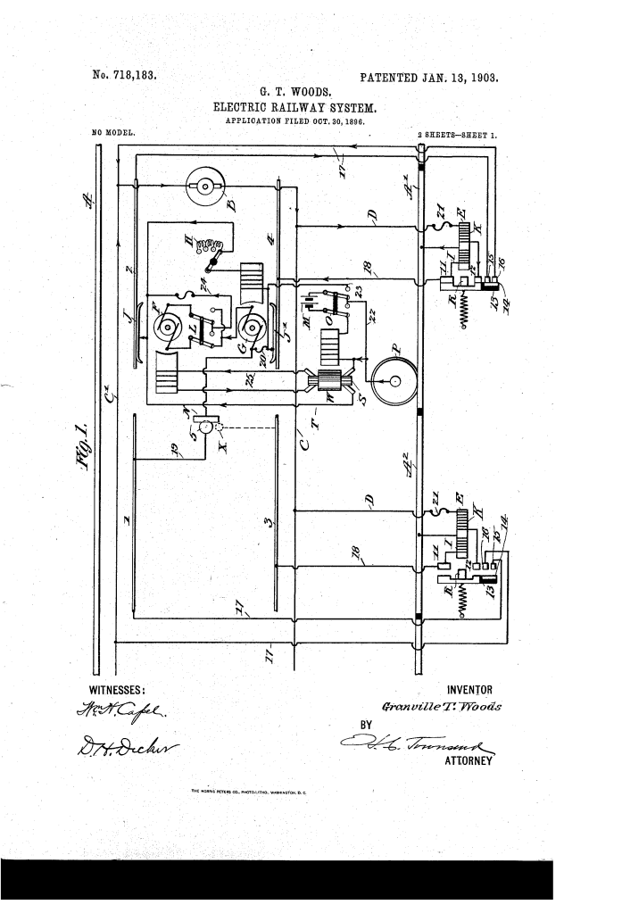
The system is a multi-layered electrical network on the car designed to initiate, sustain, and—most importantly—safely cut the power to track sections, with onboard compensation for line defects.
1. Track Power and Switching
- Sectional Working Conductors (1, 2, 3, 4): Short lengths of rail or contact blocks placed along the road, carefully insulated from each other and the ground (normally “dead”).
- Electromagnetic Switches (E): Track-side switches control the flow of current from the feeder (C) to the working conductors.
- Switch Operation (Two Coils): Each switch uses two coils:
- Pick-up Coil (I): Initially closed by a small current shunted from the main feeder or an on-board battery (M) to initially energize the magnet and close the main contacts.
- Hold Coil (K): Wired in series with the car motor (F). Once the main motor starts drawing power, the current through this coil holds the switch closed until the car passes.
2. On-Board Control and Regulation
- Two Motors on Car (F and G): The car carries two electrodynamic machines in series:
- Motor F (Working Motor): For propelling the car.
- Motor G (Regulator): Used for regulation (like a Ward Leonard system), with adjustable resistance (H) in its field circuit.
- Function: The variable voltage generated by Motor G and the constant counter EMF of Motor F vary the current supplied to the motor F, providing smooth speed regulation without wasting energy as heat.
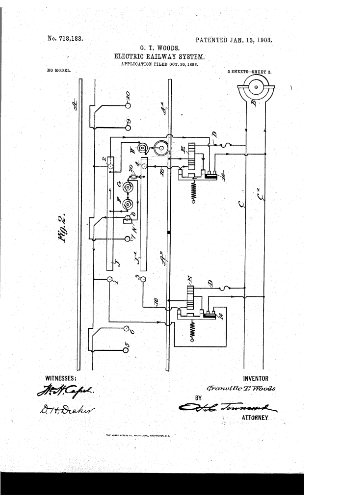
3. Safety and Fault Compensation (Key Innovation)
- Test Contact-Maker (N) and Fuse (20): A test-contact maker (N) and a single fuse (20) are placed in the motor circuit on the car. Test-contacts (5) are located along the line of way.
- Automatic Fail-Safe:
- If a switch sticks (fails to open) after the main collector (J) leaves the section, the test contact (N) passes over the live test-contact (5) connected to that section.
- This action short-circuits the motor circuit, causing the fuse (20) to blow.
- Result: The power is cut off instantly, preventing the conductor from remaining alive (a major safety hazard) and compelling the car to stop.
- On-Board Compensation (Motor-Generator W): The car carries a motor-generator (W) in the pick-up shunt circuit.
- Function: When snow, ice, or dirt increases the resistance on the track contacts, the counter EMF of the motor-generator automatically decreases, compensating for the varying resistance and ensuring the pick-up magnet still receives sufficient current to operate the switch reliably.
Concepts Influenced by This Invention
Woods’s system established foundational principles for modern electric traction and safety systems by pioneering active, real-time fault detection and compensation.
- Active Short-Circuit Safety: The most significant influence is the use of a dedicated, secondary test circuit (N) whose sole purpose is to initiate a short-circuit to trigger a protective device (Fuse 20) if a section of rail is faulty. This fail-safe principle influenced early circuit-breaker logic and is essential for safety in critical power systems.
- Adaptive Counter-EMF Regulation: The concept of using a motor-generator (W) on the car to automatically vary its own counter EMF to stabilize the current flowing to the track-side switch magnets influenced the design of sophisticated power systems that require on-board compensation for external circuit deficiencies (e.g., voltage drops, line resistance variations).
- Sectional Power and Safety Interlocking: This patent represents the highest refinement of the sectional power rail concept, ensuring maximum safety (conductor never stays live) through redundancy (two coils) and active monitoring (test contact N).
- Power Regeneration/Efficiency: The regulation achieved by dynamic voltage control (Motor G) and the use of the motor-generator (W) to supply auxiliary power influenced the long-term trend toward energy-efficient motor control.
