
Electric Railway Supply System (1893)
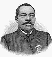
U.S. Patent No. 507,606, granted on October 31, 1893, to Granville T. Woods, describes an innovative electrical distribution framework designed to safely and efficiently power electric transit lines. Granville T. Woods, an extraordinarily prolific inventor, was a towering pioneer in electrical engineering and transportation technology.
This specific invention solved a critical hurdle in the early days of electric mass transit: how to maintain high-voltage, continuous electrical supply to moving trains via underground conduits without catastrophic power drainage, short-circuiting, or infrastructure degradation caused by moisture, rain, and environmental debris.
The Innovation: Dynamic Fluid Insulation
Early electric railways utilizing underground third rails or supply cables suffered severe power leakage whenever water seeped into the underground conduits. Woods’s breakthrough was not merely a physical barrier, but an active, pressurized defense mechanism: the continuous distribution of a fluid insulator directly to the core of the line’s supporting units.
Instead of relying solely on static glass or porcelain blocks that fail when wet, Woods designed a system that constantly pumps a medium-bodied insulating oil under pressure through a network of parallel pipes, feeding it directly into the hollow interior of every single conductor support along the line.
Why Pressurized Oil?
- Continuous Self-Healing: The insulating oil gradually percolates through a compressed, porous core, forcing out moisture and creating a water-repellent barrier.
- Leakage Prevention: By maintaining the oil under constant pressure, it blocks conductive dirt and water from bridging the gap between the live electrical line and the grounded earth.
- Targeted Control: The design features individual shut-off valves for every single insulator support, allowing maintenance crews to isolate damaged sections without disabling the entire railway circuit.
Key System Components
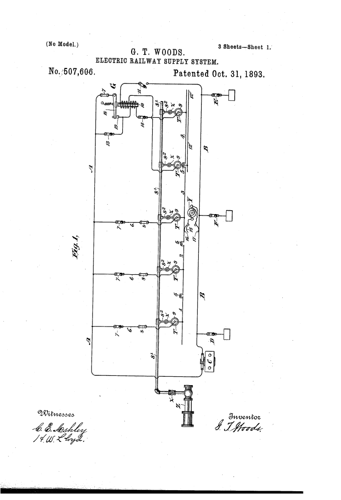
The architecture functions as a unified, self-sustaining network where hydraulic pressure protects electrical integrity:
| Component | Function |
| Main Leads (A & B) | The primary power lines connected to the central generator; Lead A feeds the system while Conductor B (often the tracks) completes the return circuit. |
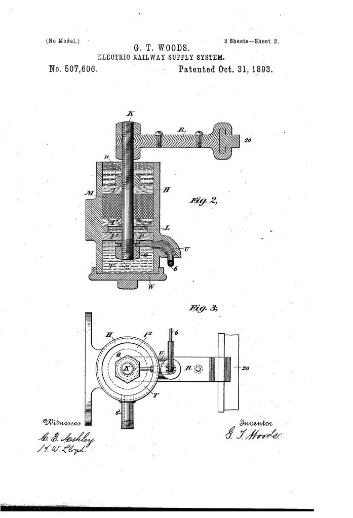
| Hollow Outer Body (H) | The non-porous shell (made of metal, glass, or porcelain) that houses the internal mechanics of each line support. |
| Porous Core (M) | A compressed inner filling made of wool, cotton, or asbestos that regulates the gradual percolation of the insulating oil. |
| Supporting Stem (K) & Arm (R) | A metallic assembly bolted securely through the porous core that holds the live work conductor in place and delivers current. |
| Parallel Supply Tube (s) | A master pipeline running the length of the railway path that receives pressurized oil from a central pump or standpipe. |
| High-Resistance Segments (5) | Specialized connector joints placed between the low-resistance work tracks to suppress heavy arcing as train brushes pass over them. |
Performance: Halting the Ground Fault
Woods’s patent outlines a distinct dual-defense operational framework to ensure that power is directed exclusively to propelling the train, maximizing system efficiency.
1. Active Hydraulic Resistance
Under standard operating conditions, the constant force applied by the central oil pump (Z) creates a continuous chemical shield around the internal stem (K). If water floods the underground open conduit, the pressurized oil actively resists displacement, maintaining structural insulation that standard dry-porcelain systems could not sustain.
2. The Isolation Switchboard
To combat the realities of system-wide wear, Woods integrated an optional ground circuit loop:
- Good Insulation Status: The system relies on the conductivity of the rails and earth to return current efficiently.
- Bad Ground Status: If a severe ground fault occurs along the main feed line, a series of specialized switches (D, E, F) can instantly disconnect the local ground loops, stopping massive power waste and saving the generator from short-circuit failures.
The Manufacturing and Mechanical Assembly
To construct a perfectly sealed, functional support unit, Woods dictated a precise configuration sequence:
- Compress the porous material (M) tightly between stiff retaining disks (I) using adjustable nuts (n, O) along the central metallic stem to establish the desired oil flow resistance.
- Lock the compressed assembly into the inner ring ledger (L) of the non-porous outer shell (H).
- Bind the main electrical tap wire (6) securely beneath the base washer to bridge a continuous circuit to the support arm.
- Seal the hollow inlet neck (U) completely by pouring in melted asphaltum or rosin, perfectly insulating the wire entry point against moisture.
- Connect the internal cavity (T) directly to the parallel oil mains via secondary tubular pipelines (s’).
About the Inventor: Granville T. Woods
Granville T. Woods was one of the most prominent and influential inventors in the history of modern transportation and electrical development.
- Patents: He held dozens of milestone patents, famously inventing the Induction Telegraph system (which allowed moving trains to communicate with stations), advanced air brake concepts, and fundamental improvements to overhead third-rail systems.
- Impact: Before Woods’s inventions, city transit was heavily reliant on horse-drawn cars or primitive, dangerous electrical lines susceptible to catastrophic grounding during rainstorms. His engineering breakthroughs paved the structural foundation for safe, underground subway networks in cities like New York and Boston.
- Legacy: Overcoming severe racial barriers of the late 19th century, Woods successfully defended his intellectual property in high-profile patent disputes—including challenges from Thomas Edison—and eventually sold several of his critical inventions to industrial titans like General Electric and Westinghouse.
Summary of Claims
The patent explicitly claims:
- A system of electrical distribution combining a generator, live conductors, insulating supports, and a parallel pipeline supplying fluid insulation directly to those supports.
- A hollow insulating structure utilizing a compressed, non-electric conducting porous substance to filter and regulate liquid insulation.
- The integration of individual mechanical valves to cut off the supply of liquid insulation from any distinct, independent insulator along the line.
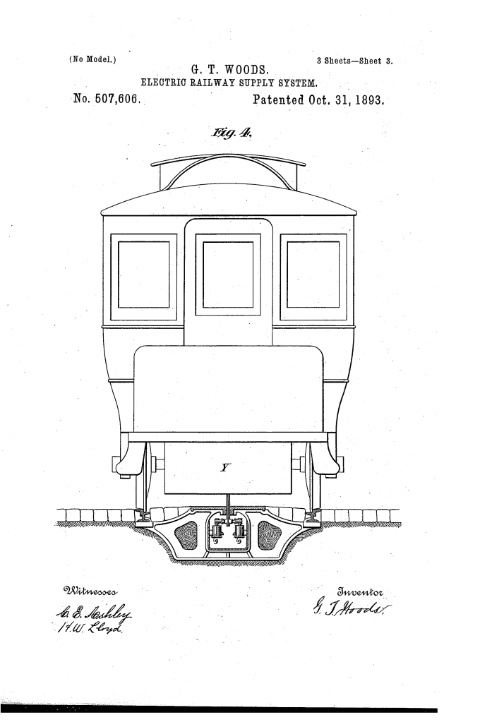
- An underground open conduit configuration using a traveling motor-car equipped with automated contact brushes to maintain a sealed power supply circuit.
