
Draft Regulator (1893)
U.S. Patent No. 491,082, granted on February 7, 1893, to Phillip W. Cornwell, describes an improved draft-regulating system designed for the flues of stoves, furnaces, and locomotives. Cornwell, an inventor residing in Brockton, Massachusetts, focused this design on increasing the mechanical longevity and thermal efficiency of residential and industrial heating systems.
This specific invention solved a persistent flaw in 19th-century stove architecture: how to prevent internal damper components from warping, burning out, or melting when constantly exposed to the direct, concentrated heat at the center of a exhaust flue.
The Innovation: The “Split-Path Perimeter Lift”
In Cornwell’s previous designs, the lever mechanism extended directly into the dead center of the flue to raise and lower a supplemental damper ring. However, because the center of a flue experiences the highest localized temperatures, these straight linkages rapidly deteriorated.
Cornwell’s breakthrough was an architectural redesign that completely bypassed the center of the exhaust stream. By splitting the mechanical lift into a crescent-shaped architecture, the invention rerouted all moving parts away from the thermal core, utilizing the cooler perimeter zones near the pipe walls.
Why the Curved Perimeter Design?
- Thermal Protection: It shifts the entire mechanical load away from the center of the flue, protecting the metal from premature failure caused by intense heat.
- Increased Airflow: By eliminating the bulky central bail found in traditional models, it frees up internal workspace, directly increasing the overall draft capacity of the flue.
- Rust-Resistant Articulation: It substitutes traditional, tight-fitting mechanical hinges with open, loose-fitting slotted joints. These joints provide smooth operation while preventing soot and rust from seizing the mechanism.
Key Mechanical Components
The apparatus relies on a series of perimeter-mapped linkages to control exhaust flow:
| Component | Function |
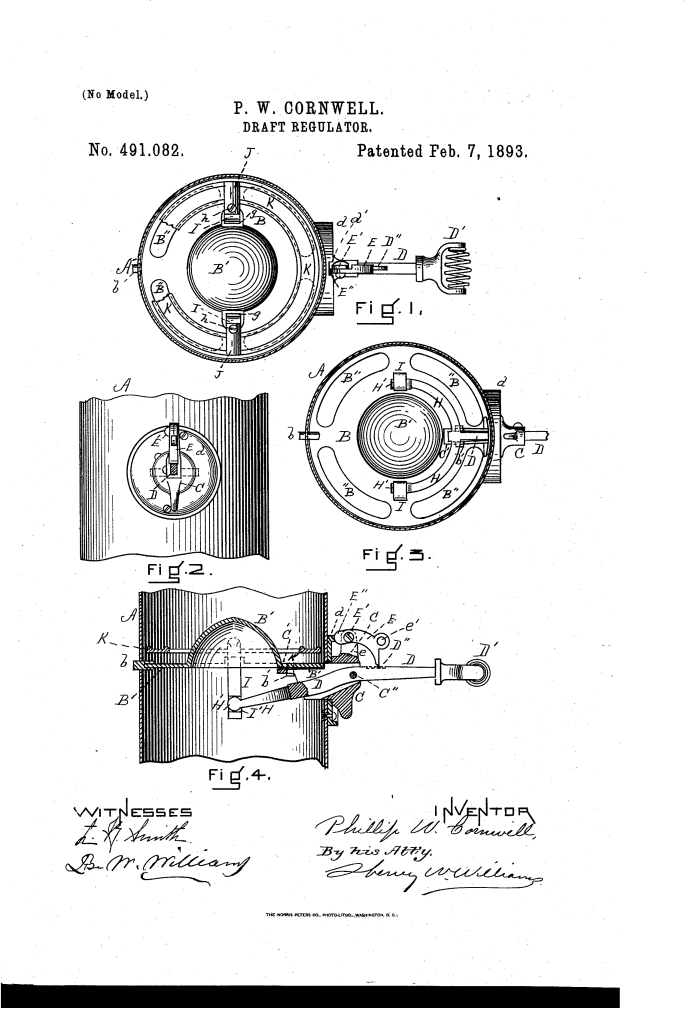
| Main Damper (B) | A rotatable circular plate mounted within the flue, featuring a central dome ($B^1$) and a series of curved exhaust slots ($B^2$) near its outer edge. |
| Supplemental Ring (K) | A secondary ring damper that sits flat against the main damper, moving vertically to seal or open the perimeter exhaust slots. |
| Semicircular Bar (H) | A crescent-shaped attachment fixed to the control lever that splits the mechanical lifting force into two paths along the pipe wall. |
| Circular Enlargements ($H^1$) | Rounded, bulbous ends on the semicircular bar that form loose, self-cleaning joints inside the vertical rods. |
| Vertical Guide-Rods (I) | Two parallel bars that pass through side openings ($g$) in the main damper to connect the lower lever assembly directly to the upper ring. |
| Locking Pawl (E) | An external, weighted safety latch equipped with a rear heel ($E^2$) that simultaneously locks both the main rotation and vertical height. |
How the Apparatus Functions
The operational sequence allows the operator to fine-tune air intake and lock the safety assemblies safely from outside the hot exhaust pipe:
1.Lever Articulation:External Input.
The operator manipulates the external handle (D1) of the actuating lever, pivoting the mechanism within the hollow thimble (C) driven into the flue wall.
2.Force Splitting:Perimeter Separation.
The pivoting motion swings the internal end of the lever. This pushes the attached semicircular bar (H), moving the mechanical force outward along the interior perimeter of the pipe.
3.Parallel Guide Lift:Vertical Transit.
The rounded ends (H1) of the curved bar slide through the lower slots (I1) of the vertical guide-rods, pushing them straight up through the side channels of the main damper plate.
4.Supplemental Ring Adjustment:Draft Regulation.
The rising guide-rods lift the supplemental ring (K) away from the main plate, opening or closing the peripheral slots (B2) to perfectly regulate the stove’s draft.
5.Dual-Axis Registration:Safety Lock.
The external pawl (E) drops into the notches of the lever to fix the ring height. Concurrently, the pawl’s rear heel (E2) drops into a notch (d1) on the stationary outer plate, locking the main damper against unwanted rotation.
Performance: Thermal Longevity
Cornwell’s patent demonstrated a significant leap forward in component lifespan compared to central-bail regulators of the era.
Comparative Failure and Airflow Metrics:
- Central-Bail Regulators: Typically suffered severe warping or metal burnout within months due to direct exposure to the thermal core. The central linkage also restricted exhaust area by roughly 10–15%.
- Cornwell Perimeter System: Kept all structural elements out of the central blast zone. This alteration effectively eliminated heat-induced deformation while leaving 100% of the central flue space open for maximum draft efficiency.
About the Inventor: Phillip W. Cornwell
Phillip W. Cornwell was a dedicated late-19th-century mechanical designer based out of Brockton, Massachusetts—a bustling industrial manufacturing hub during the post-Civil War era.
- Iterative Design: Cornwell specialized in thermodynamic control systems. This 1893 patent was a direct, field-tested upgrade to his original 1888 design (U.S. Patent No. 390,284), reacting to consumer feedback regarding component burnout.
- Maintainability Standard: Recognizing the harsh environment inside coal and wood-burning flues, Cornwell engineered this entire system to be completely modular. Every interlocking component could be pulled apart, cleared of creosote, or duplicated without requiring the structural disassembly of the stove-pipe itself.
Summary of Claims
The patent explicitly claims:
- The combination of a main damper with vertical guide-rods positioned exclusively on opposite sides of the flue center, driven by a curved perimeter bar.
- A vertical lift assembly utilizing guide-rods with bottom slots (I1) that interact loosely with enlarged curved ends (H1) to provide a non-binding, rust-resistant joint.
- An external control housing featuring a notched lever, a rotating thimble, and a single notched security disk (d) that allows a lone pawl to lock both horizontal dampening and vertical draft positions simultaneously.
