
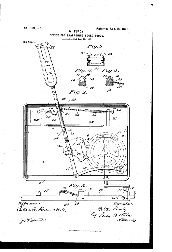
Device for Sharpening Edged Tools (1898)
U.S. Patent No. 609,367, granted on August 16, 1898, to Walter Purdy, details a specialized mechanical sharpener designed to hone razors and other fine-edged blades with precision. Walter Purdy, an inventor based in Somerset, Pennsylvania, sought to overcome the primary technical challenges of manual razor maintenance: replicating the skilled barber’s elliptical stroke while automatically flipping the blade edge-forward on every pass.
This invention improved upon Purdy’s earlier patent (No. 570,337) by introducing an automated rollover mechanism, eliminating uneven blade wear and human error during sharpening.
The Innovation: The Elliptical Stroke and Automatic Blade Reversal
Manual razor stropping and honing require a specific figure-eight or elliptical stroke to prevent creating flat spots or micro-grooves along the cutting edge. Furthermore, the blade must lead with its edge to achieve a true, burr-free bevel, requiring it to flip over at the end of each stroke.
Purdy solved both challenges mechanically by combining an eccentric gear drive with a dual-spring tension system that flips the tool holder automatically at each limit of travel.
Why the Automatic Reversal?
- Edge-Leading Motion: Ensures that the cutting edge always travels in advance of the blade body across the hone, preventing burr buildup and replicating expert hand honing.
- Elliptical Sweep: Moves the blade in a continuous oval path rather than a straight back-and-forth line, distributing wear evenly across both the tool and the stone.
- Controlled Rotation: Uses detent sockets and a leaf spring to prevent free-spinning or premature blade flips, locking the tool firmly into position until the exact stroke endpoint is reached.
Key Mechanical Components
The apparatus combines an eccentric drive train, a pivoting carrier, and opposing tension springs to govern the blade’s travel and rotation:
| Component | Function |
| Casing and Base Plate (1, 2) | The primary rigid frame supporting the internal drive gears, guide rail, and bracket mountings. |
| Drive Gearing (3, 4, 5, 6, 7, 8, 9) | Hand-cranked bevel and spur gears that translate manual rotational input into the drive shaft. |
| Star-Wheel and Main Arm (11, 12, 14) | Eccentric star-wheel mechanism that imparts an oval or elliptical sweep to the pivoting main arm. |
| Rotatable Tool-Carrying Arm (16) | Seated within the concaved front end of the main arm, free to rotate axially between two collar stops. |
| Limiting Pin and Sockets (19, 20) | A rear radial pin that drops into opposing sockets in the main arm to limit blade rotation strictly to 180 degrees. |
| Retaining Leaf Spring (21) | Bears down on the radial pin to resist premature movement, holding the blade steady until maximum spring tension trips it. |
| Opposing Springs and Brackets (22, 23, 24, 25, 26) | Paired coiled springs attached via chains to eyes on the carrier arm; their opposing tension forces the blade rollover at each stroke extremity. |
| Clamping Tool-Holder (27, 28) | Two serrated plates adjusted by screw-bolts to hold the razor blade securely during operation. |
| Support Rail (29) | A raised curved track on the front of the plate that supports the weight and motion of the swinging arm. |
How the Apparatus Functions
The mechanical cycle operates through a continuous, self-reversing four-step sequence driven by a single hand crank:
| Step | Action | Mechanical Purpose |
| 1. Placement | The razor blade is clamped between the serrated holder plates (27) with its cutting edge facing right, placed in contact with the underlying hone. | Secures the blade rigidly at the proper honing angle without slipping. |
| 2. Elliptical Stroke | Turning the handle (7) drives the star-wheel (11), sweeping the main arm (14) to the right along an elliptical path. | Advances the blade cutting-edge-first over the hone, reproducing proper manual stropping geometry. |
| 3. Tension Loading | As the arm moves right, the right-hand spring (24) relaxes while the left-hand spring is stretched under tension via screw-rod (25). | Builds sufficient mechanical force to overcome the leaf-spring detent holding the carrier pin. |
| 4. Automatic Flip | At the extreme right limit of stroke, left-hand spring tension overcomes leaf spring (21); the carrier arm (16) rotates 180 degrees until pin (19) hits socket (20). | Instantly flips the razor edge to face left, readying it for the return stroke in the opposite direction. |
Historical and Industrial Impact
Walter Purdy’s automatic sharpener represents a critical transitional development in late 19th-century mechanical automation for everyday personal grooming and industrial tool maintenance:
- Democratizing Precision Honing: In the late 1800s, maintaining straight razors required daily skill and frequent trips to professional barbers or cutlers. Devices like Purdy’s allowed untrained users to achieve a consistent edge without rounding the bevel.
- Mechanical Edge Preservation: Moving the blade across the hone in an ellipse while maintaining positive edge advance prolonged the life of expensive carbon steel cutlery, preventing uneven hollowing of the stone and razor.
- Self-Governing Mechanics: The design utilized kinetic momentum and spring tension rather than complex micro-gearing to execute the blade reversal, making it durable, serviceable, and resilient against abrasive hone dust.
About the Inventor: Walter Purdy
Walter Purdy was a late 19th-century inventor residing in Somerset, Somerset County, Pennsylvania. Working during an era marked by the rapid mechanization of domestic and small-workshop tasks, Purdy focused on mechanical kinematics, tool-sharpening fixtures, and precision edge-holding devices. His sequential patents in the late 1890s demonstrated practical mastery of eccentric gear linkages and mechanical automation designed for widespread commercial utility.
Summary of Claims
The patent explicitly claims:
- The combination of a frame, a fixed hone, and a carrying arm imparting an oval or elliptical path of travel to an edged tool.
- A rotatable tool-carrying arm coupled to opposing resilient members (springs) that automatically reverse the blade’s edge presentation at each travel limit.
- A stop mechanism comprising a radial pin, paired socket detents, and a retaining leaf spring to lock the blade rigidly in position against accidental displacement during each stroke.
