
GASAR: Device for Gas Amplification by Stimulated Emission and Radiation (1966)
U.S. Patent No. 3,257,620, granted on June 21, 1966, to Louis W. Roberts (assigned to Metcom, Inc.), describes a radio frequency electromagnetic wave amplifier that harnesses an ionized gas plasma rather than hard-vacuum electron beams to achieve high-power, broadband amplification at kilomegacycle and millimeter wavelengths.
Prior microwave amplifiers—such as klystrons, magnetrons, and traveling-wave tubes (TWTs)—relied on modulating electron streams inside high-vacuum environments. These legacy systems suffered from severe physical constraints: klystrons were band-limited, magnetrons could not easily alter frequencies, and traveling-wave tubes required fragile, precision-machined slow-wave helical structures that were costly and difficult to cool. Roberts solved these problems by introducing the “GASAR,” an amplifier that eliminates the need for delicate internal delay lines or finely focused electron streams entirely.
The Innovation: The Non-Maxwellian Plasma State
In a standard, steady-state ionized gas, free electrons exhibit a classical Maxwellian velocity distribution where the radiation temperature matches the mean kinetic temperature. In that state, absorption dominates.
Roberts discovered that by manipulating cathode emission, grid potentials, and an axial magnetic field, he could drive the plasma electrons into a non-Maxwellian velocity distribution. Under these conditions, the incoherent radiation temperature exceeds the mean kinetic temperature, producing a negative radiation temperature and a negative absorption coefficient. When an incoming radio frequency wave travels through this plasma at substantially free-space velocity, stimulated emission exceeds absorption—transferring raw energy directly from the plasma into the propagating wave.
Why a Plasma Amplifier?
- Free-Space Propagation: Unlike traveling-wave tubes, the GASAR does not require physical helical coils to slow the radio wave down to match electron velocities.
- Broad Bandwidth: Because amplification does not depend on electron transit time or tuned resonant cavities, the operational frequency can span exceptionally wide bandwidths.
- High Power Capacity: Without delicate internal microwave circuits to melt or overheat, the plasma medium can handle large power throughputs without breakdown.
- Millimeter Wave Capability: Frequency is governed by bulk plasma parameters (density, gas selection, and magnetic field) rather than microscopic component tolerances.
Key Structural Components
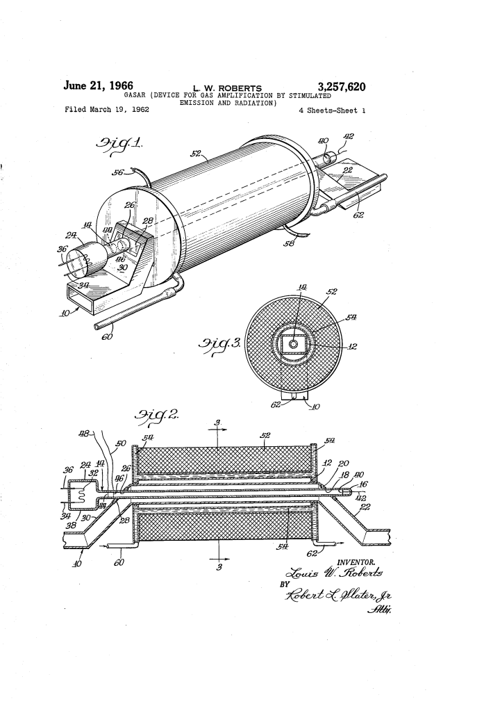
The GASAR integrates an ionized discharge vessel directly into standard microwave transmission lines:
| Component | Function |
| Dielectric Tube (14 / 154) | Quartz or high-melting-point glass tube holding an inert gas (argon, xenon, or krypton) at 3 to 20 microns pressure. |
| Broad Cathode (32 / 126 / 170) | Large-area electron emitter (e.g., oxide-coated tungsten mesh) providing a dense, unfocused supply of free electrons. |
| Screen Grids (44, 46 / 136 / 176, 180) | Coarse wire grids placed near the cathode to accelerate and adjust electron velocities into the non-Maxwellian profile. |
| Anode (40 / 108 / 184) | Positively charged collector plate or metal cylinder positioned at the opposite end of the discharge path. |
| Magnetic Solenoid / Magnets (52 / 142–148 / 164) | External coil or permanent Indox V rings supplying an axial magnetic field to restrain electron trajectories without beam focusing. |
| Liquid Cooling Jacket (54 / 86 / 162) | Concentric water jacket that dissipates thermal energy generated by the solenoid and high-frequency wave propagation. |
Physical Implementations
Roberts detailed four mechanical adaptations to integrate the GASAR across different high-frequency transmission systems:
- Rectangular Waveguide: An offset rectangular guide (10, 12) mounts the dielectric quartz tube (14) symmetrically through plane dielectric panels (20, 28) enclosed by an external solenoid (52).
- Ridge Waveguide: Longitudinal ridges (90, 92) inside the guide allow the transmission of significantly longer wavelengths (such as L-band waves in an assembly sized for S-band) without increasing overall physical dimensions.
- Flexible Coaxial Guide: Utilizes a central hollow cathode (126) mounted between expandable metal bellows (122, 124) with permanent Indox V magnet discs (142–148) and an outer cylindrical conductive anode sleeve (108).
- Rigid Coaxial Guide: Features a quartz tube (154) seated coaxially inside hollow central inner conductors (158, 160) surrounded by a rigid outer casing (156) and an annular solenoid (164).
Operational Mechanism
The GASAR follows a precise sequence to establish amplification:
- Plasma Ignition: An inert gas (such as argon at 10 microns) is ionized by current emitted from the heated mesh cathode.
- Velocity Shaping: The first screen grid accelerates the emitted electrons, while the second grid and plate voltage establish an uneven velocity profile.
- Magnetic Confinement: Solenoid current is adjusted to generate an axial magnetic field (e.g., approximately 1150 gauss) that guides electron motion and facilitates Bremsstrahlung or cyclotron radiation mechanisms.
- Wave Coupling: Incident electromagnetic waves enter the waveguide at normal velocity, stimulate emission from the non-Maxwellian plasma, and exit with amplified power.
Historical and Scientific Impact
Louis W. Roberts’s development of the GASAR represented a critical step in Cold War microwave physics, particularly for military radar, countermeasure equipment, and satellite communications.
- Bypassing Machining Limits: Prior high-frequency microwave tubes required sub-millimeter machining tolerances that were extraordinarily expensive and prone to mechanical failure. Roberts proved that plasma dynamics could replace mechanical delay lines.
- Radiation Physics Breakthrough: The patent operationalized emerging theoretical work from MIT physicists Sanborn C. Brown and G. Bekefi, translating non-Maxwellian plasma theory and negative absorption into a working microwave hardware architecture.
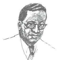
About the Inventor: Louis W. Roberts
Louis Wright Roberts was an accomplished African American physicist, mathematician, and inventor whose career shaped microwave electronics and aerospace navigation.
- Academic and Industrial Leadership: Educated at Fisk University and the University of Michigan, Roberts served as chief scientist and executive at several prominent microwave research enterprises, including Metcom, Inc., and Microwave Associates.
- Public Service and NASA: Roberts later served as the Director of Energy and Environment at the U.S. Department of Transportation’s Transportation Systems Center and held senior technical leadership roles at NASA’s Electronics Research Center in Cambridge, Massachusetts.
- Prolific Inventor: Holding multiple patents in microwave tubes, plasma devices, and radar components, Roberts was an internationally recognized authority on high-frequency electromagnetic propagation and optics.
Summary of Claims
The patent explicitly claims:
- An apparatus for amplifying electromagnetic waves moving at substantially free-space velocity through a waveguide without slow-wave structures.
- The generation and use of an electron plasma having an induced non-Maxwellian energy distribution to produce negative radiation absorption.
- The structural combination of an elongated dielectric plasma vessel positioned longitudinally within rectangular, ridge, or coaxial waveguides.
- The application of an external axial magnetic field and spaced screen grids to restrain and shape the electron distribution within the plasma.
