
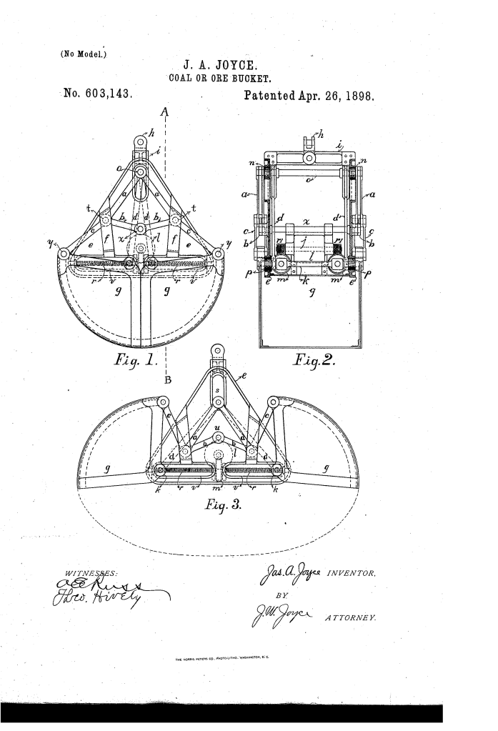
Coal or Ore Bucket (1898)
U.S. Patent No. 603,143, granted on April 26, 1898, to James A. Joyce, describes an electrically or mechanically powered clamshell-style scoop engineered for heavy industrial material handling, specifically targeting the rapid excavation and transfer of bulk coal and metallic ore.
James A. Joyce, an inventor based in Cleveland, Ohio—a central boomtown for Great Lakes shipping and iron production at the turn of the century—addressed a major mechanical inefficiency in standard hoisting scoops: conventional cable-and-gravity buckets tended to ride up or slip over compacted bulk cargo rather than biting deeply into the load. Joyce engineered a screw-driven linkage assembly that forces the bucket halves along an elliptical cutting trajectory, digging inward and upward under mechanical leverage.
The Core Innovation: The Elliptical Scraping Motion
Rather than swinging on a single, fixed central pivot that merely pinches shut, the halves of Joyce’s bucket are guided through a coordinated system of horizontal and vertical traveling beams driven by motorized power screws.
As the drive mechanism activates, the cutting edges of the bucket do not follow a simple arc; they trace the path of an ellipse. This controlled geometry forces the leading edges to slice horizontally into the coal or ore heap and scoop it upward, packing the interior cavity full before the sections meet.
Technical Components
The structural rigidity and power transfer of the assembly depend on an integrated mechanical framework:
| Component | Function |
| Frame (e) and Cross-Arm (d’) | Forms the structural chassis of the bucket; houses the guide tracks and provides hoisting points (h) for cranes or conveyors. |
| Motive Power (l) | An onboard electric motor (or alternate power source) configured with a horizontal drive shaft. |
| Worm Gears and Drive Screws (r, m) | Worms (r) engage worm-wheels (m) mounted to heavy horizontal screw-shafts fitted with thrust bearings. |
| Transverse Beams (k) | Threaded cross-members riding on the screw-shafts; they connect to the bucket shells and travel horizontally along frame slots (c). |
| Upper Beam (o) and Guide Rollers (n) | A vertically traveling cross-beam guided along vertical frame slots (s) to balance load distribution during closure. |
| Link System (a, b, c, d) | Articulated linkages connecting beams k and o to the bucket shells (g) to dictate the elliptical cutting path. |
| Guide Plates (f) | Lateral guide brackets mounted to the outer frame to eliminate side-to-side swaying under unbalanced industrial loads. |
How the Bucket Functions
The scoop completes a full dig-and-dump cycle through a reversible mechanical sequence:
| Step | Action | Mechanical Result |
| 1. Positioning | Open bucket is lowered onto coal or ore pile via hoisting attachment (h). | Jaws rest open; drive assembly remains unengaged. |
| 2. Motor Drive | Motor (l) drives shaft worms (r), turning worm-wheels (m) and rotating the main drive screws. | Converts high-speed motor rotation into high-torque linear screw thrust. |
| 3. Inward Traverse | Threaded beams (k) travel inward along horizontal slots (c); beam (o) moves vertically. | Guides the lower bucket edges along an elliptical scraping trajectory. |
| 4. Digging and Closure | Bucket halves (g) bite into the bulk material, cutting downward and scooping inward. | Buckets seal tightly together, fully packed with ore or coal for crane hoisting. |
| 5. Discharge | Upon transport to the hopper or railcar, the motor is reversed. | Screws push beams (k) outward, opening bucket halves (g) and dumping the contents instantly. |
Industrial and Operational Impact
Patented at the height of the industrialization of the Great Lakes shipping ports, Joyce’s powered coal and ore bucket bypassed several key failure points of 19th-century bulk loading:
- Direct Mechanical Bite: By relying on positive screw drive rather than crane cable tension alone, the jaws could not simply slide over dense ore piles, ensuring maximum payload on every pass.
- Self-Contained Motorization: Joyce integrated the motive power directly onto the bucket chassis, making it suitable for modernizing electrified docks, industrial gantry cranes, and steamship unloading terminals.
- Lateral Stability: The use of dedicated alignment slots and guide plates prevented bucket misalignment and binding, common risks when moving heavy, uneven bulk commodities.
About the Inventor: James A. Joyce
James A. Joyce resided in Cleveland, Cuyahoga County, Ohio, during an era when the city served as a primary hub linking the iron ranges of the upper Midwest to the steel mills of Pennsylvania and the Ohio Valley. His patents contributed to the rapid mechanization of heavy material handling, standardizing high-capacity automated transfer solutions across rail yards and maritime docks.
Summary of Claims
The patent explicitly claims:
- The combination of a supporting frame, movable guide beams (k and o), and bucket sections interconnected by articulated links (a, c, d, and b) to direct the jaw movement.
- A power-operated horizontal shaft equipped with right and left worm-screws (r) driving worm-wheels (m) to actuate the guide beams inward or outward.
- The application of an onboard electric motor mounted within the frame to power the multi-axis linkage system, enabling controlled cutting, scraping, and emptying of bulk material.
