
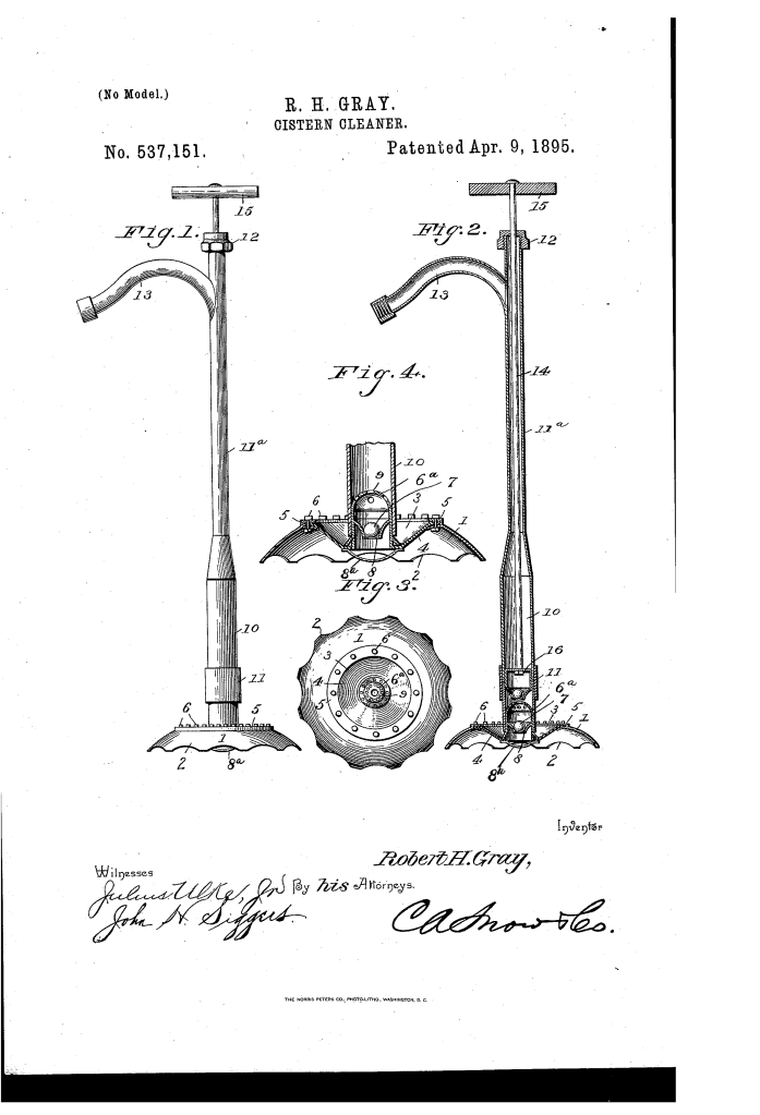
Cistern-Cleaner (1895)
U.S. Patent No. 537,151, granted on April 9, 1895, to Robert H. Gray of Lexington, Kentucky, details a mechanical solution designed to clean mud, sediment, and other accumulations from the bottom of ordinary water cisterns.
In the late 19th century, residential cisterns were vital for collecting and storing rainwater, but they routinely gathered thick layers of organic debris. Gray’s invention solved a primary industrial and domestic issue: how to thoroughly pump out heavy bottom-sediment without unnecessarily agitating the surrounding water column, while allowing the operator to pump from any comfortable angle above ground.
The Core Design: The Dual-Flexible Interface
The mechanical brilliance of Gray’s cistern cleaner lies in its ability to maintain a perfectly flat, unbroken suction seal on the cistern floor, even if the pump handle above is tilted, angled, or moved. This was achieved through a unique dual-flexibility design.
- The Flexible Cup Cover (4): The bottom suction cup features a top membrane made of flexible rubber cloth. Instead of a rigid metal housing that would break its seal if the pump shifted, this rubber cover flexes dynamically to absorb vertical and lateral movement.
- The Flexible Cylinder Joint (11): Located just above the intake valve, Gray integrated a short section of flexible rubber tubing directly into the pump cylinder. This acts as a universal joint, allowing the long upper discharge tube to bend completely out of alignment without transferring torque to the base.
How the Apparatus Functions
The process relies on a tight localized seal and a standard reciprocating pump action to draw heavy impurities directly off the floor:
| Step | Action | Mechanical Purpose |
| 1. Placement | The cleaner is lowered until the suction cup (1) rests flat on the cistern floor. | Positions the unit directly over the debris layer. |
| 2. Grounding | A curved rest bar (8a) beneath the valve cage bears the physical weight of the pump. | Relieves the flexible rubber cover from structural strain and prevents tearing. |
| 3. Intake Seal | Water and mud enter exclusively through the scalloped lower edge (2) of the cup. | Restricts the intake zone to the very bottom, preventing clean water above from being disturbed. |
| 4. Upstroke | The handle (15) is pulled, raising the valved plunger (16) inside the cylinder. | Creates suction that lifts a ball valve (7), drawing mud up into the cylinder (10). |
| 5. Downstroke | The handle is pushed down, closing the ball valve over its tapered seat (8). | Prevents the muddy mixture from flushing back down into the cistern, forcing it up and out of the discharge spout (13). |
Key Technical Components
The assembly balances rigid structural components with flexible materials to optimize fluid dynamics:
- Scalloped Suction Cup (1): A shallow base featuring perimeter openings that allow heavy, thick mud to enter the suction stream evenly.
- Fastening Ring (5): A secure clamping ring that rivets the flexible rubber cover to the cup opening, creating a permanent, watertight joint.
- Valve Cage (6a) & Ball Valve (7): A central check-valve housing equipped with a perforated top plate (9) that allows free fluid passage while capturing the ball to maintain uniform pumping cycles.
- Discharge Tube (11a) & Stuffing Box (12): The upper column that delivers waste to the surface. The stuffing box creates a tight seal around the moving plunger rod to prevent messy surface leakage during operation.
Historical and Practical Impact
Robert H. Gray’s invention provided significant utility to urban and rural infrastructure during an era before centralized, treated municipal water systems were common.
- Preservation of Water Quality: Traditional cleaning methods often required completely draining a cistern or using heavy scrapes that stirred up sediment, rendering the remaining water unusable for days. Gray’s device targeted only the contamination zone.
- Ergonomic Efficiency: Cistern openings were often narrow or awkwardly positioned. The flexible rubber joint meant a worker could operate the pump at an angle from a dry, stable position above ground rather than standing directly over or inside the well.
- Mechanical Simplicity: By utilizing a simple ball check valve combined with affordable rubber materials, Gray created a tool that was highly efficient yet durable enough to handle coarse, abrasive subterranean debris.
About the Inventor: Robert H. Gray
Operating out of Lexington, Fayette County, Kentucky, in the post-Reconstruction South, Robert H. Gray was an inventor focused on solving everyday domestic and municipal engineering challenges. His work on this apparatus demonstrates a sophisticated grasp of fluid mechanics, pressure sealing, and ergonomic design, contributing directly to the evolution of sanitation and maintenance tools in the late 19th century.
Summary of Claims
The patent explicitly claims:
- A shallow suction cup combined with a flexible cover, connected directly to a hand pump cylinder.
- The specific combination of a suction cup with a scalloped lower edge and a flexible top cover.
- The integration of a flexible joint within the pump cylinder to allow multi-directional movement without disrupting the suction base.
- A central valve cage fitted with a curved structural rest bar to sustain the weight of the pump mechanism on the cistern floor.
