
Automatic Car-Coupling (1892)
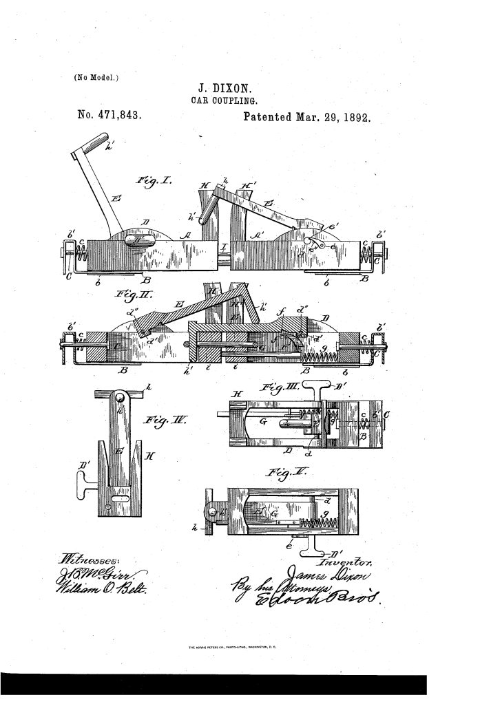
U.S. Patent No. 471,843, granted on March 29, 1892, to James Dixon, introduces a refined automatic coupling system designed to improve safety and efficiency in the railroad industry. During this era, manual car coupling was one of the most dangerous jobs in railroading; Dixon’s invention sought to eliminate the need for workers to stand between moving cars to drop a pin by hand.
This invention provided a “simple and effective” mechanism where each draw-head carried its own gravity-fed coupling pin, allowing cars to lock together instantly upon impact.
The Innovation: The “Gravity-Trigger” Mechanism
The core of Dixon’s design is the transition from manual labor to mechanical automation. The system relies on a spring-actuated trigger that holds the coupling pin in “ready” mode until the exact moment of contact.
1. The Pusher-Bar (G)
A rod extends through the draw-head and projects out the front. This bar is backed by a coiled spring (g) that keeps it under tension.
2. The Support Trigger (F)
Attached to this pusher-bar is a pointed arm or trigger. When the coupler is set, this trigger sits inside a slot on the underside of the coupling pin (E), holding it in an elevated, “cocked” position.
3. Automatic Release
As an approaching car strikes the projecting pusher-bar, it forces the rod backward. This movement pulls the trigger out from under the coupling pin, allowing gravity to drop the pin into the socket of the opposite car’s draw-head.
Key Mechanical Components
Dixon’s coupler is a rugged assembly where the pivot and the lock work in tandem to ensure the cars stay connected under the heavy jars of rail travel.
| Component | Function |
| Pivoted Coupling Pin (E) | The primary locking member that drops by gravity to secure the two cars. |
| Pusher-Bar (G) | The mechanical sensor that detects the “hit” from the other car and triggers the coupling. |
| Pivot-Pin (d) & Key | A specialized pin with an integral key that ensures the pivot turns in perfect sync with the coupling pin. |
| Detent (e) | A safety latch pivoted on the side of the draw-head that locks the pivot-pin in place to prevent accidental uncoupling. |
| U-Shaped Spring (b’) | An inverted cushion at the rear of the draw-head that absorbs the “jar” or shock of the cars colliding. |
Performance: Safety and Shock Absorption
Beyond the coupling itself, Dixon focused on the durability of the equipment and the safety of the operation:
- Safety Locking: The inclusion of the detent ensures that once the pin drops, an “unusual jar” won’t cause it to bounce out of the socket.
- Shock Mitigation: By using a combination of a slotted plate and a coiled spring (c) on the mounting bolt, the draw-head can move longitudinally. This “spring-slide” action prevents the heavy iron components from shattering during high-impact couplings.
- Manual Override: Recognizing the transitional nature of the era, Dixon included a standard link (I) and pins (i) so the car could still be coupled to older, non-automatic rolling stock.
The Manufacturing Design
The draw-head was designed for industrial durability, featuring:
- Aligned Bearings (D): Cast directly into the middle of the draw-head to provide a sturdy housing for the pivot.
- Outwardly-Flared Uprights (H): These guide the incoming pin into the socket, providing a wide “target” area for the coupling pin to land.
- Keyway Integration: The coupling pin and pivot-pin are rigidly secured via a keyway (d2), ensuring that the external handle always reflects the true position of the internal pin.
About the Inventor: James Dixon
James Dixon was an inventor based in Cincinnati, Ohio (Hamilton County). His work in the late 19th century placed him among a group of innovators focused on solving the “death-trap” nature of early American railroading. By automating the coupling process, Dixon’s design contributed to the broader movement of railroad safety that eventually led to federal mandates for automatic couplers across all interstate commerce.
Summary of Claims
The patent explicitly claims:
- A pivoted coupling pin keyed to a pivot-pin with a dedicated locking detent.
- The use of a spring-controlled pusher-bar and trigger to support the pin in an elevated position.
- The specific inverted U-shaped spring cushion at the rear of the draw-head to manage impact forces.
- The combination of upright pieces (H) forming a socket to receive and hold the cross-piece of the coupling pin.
