
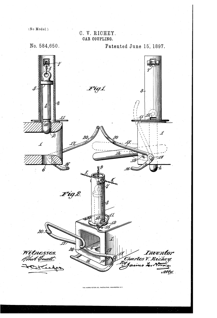
Car Coupling (1897)
U.S. Patent No. 584,650, granted on June 15, 1897, to Charles V. Richey (assignor of one-third to Leonard C. Bailey), details an automatic attachment mechanism designed for standard link-and-pin railroad car couplings. Charles V. Richey, an inventor based in Atlanta, Georgia, devised a mechanical solution to improve the safety and automation of rail operations during an era when manual coupling was one of the most hazardous jobs in the railroad industry.
This invention solved a critical problem in 19th-century rail transport: how to adapt existing, ordinary draw-heads into fully automatic couplers without requiring brakemen to physically step between moving train cars to guide the link or drop the pin.
The Innovation: The Dual-Action Lever and Latch Mechanism
Traditional link-and-pin setups required a worker to hold the link level so it would enter the opposing draw-head, then drop the pin in place at the exact moment of impact. Richey’s design introduced a coordinated system of external attachments that elevated the link and dropped the pin automatically upon contact between two approaching cars.
- The Circumferential Pin Groove and Spring-Latch (10, 11)The vertical coupling-pin (4) features an annular groove (10) cut entirely around its lower circumference.
- 360-Degree Engagement: Because the groove extends around the entire pin, the latch catches and holds the pin elevated regardless of whether the pin rotates in its tubular guide (3).
- Spring-Latch (11): A stout spring-wire anchored to the draw-head features a projection (12) that extends through an opening (13) in the pin-guide to support the raised pin until tripped.
- The Bail-Shaped Lever and Link-Lifter (16, 17)To ensure the loose link enters the opposing draw-head smoothly, Richey mounted an upwardly and forwardly projecting bail-shaped lever (17) to the sides of each draw-head.
- Link Alignment: As cars approach, opposing levers strike each other and swing backward, simultaneously raising a pivoted link-lifter (16) that positions the link at the exact height required for insertion.
- Pin Release: Further backward travel of the lever forces an inward bend (20) against the spring-latch (11), withdrawing the projection (12) and allowing the pin to drop via gravity into the link.
How the Mechanism Operates
The automatic coupling sequence occurs in distinct, mechanical stages as two cars come together:
| Stage | Action | Functional Purpose |
| 1. Preparation | Coupling-pin (4) is pulled up; spring-latch projection (12) snaps into groove (10). | Holds the pin securely in an elevated, pre-set position. |
| 2. Approach | Opposing bail levers (17) make contact and begin swinging backward. | Initiates the movement of the linked lifting components. |
| 3. Link Elevation | Pivoting link-lifters (16) swing upward beneath the inserted link (14). | Aligns the link horizontally so it smoothly enters the opposing draw-head. |
| 4. Tripping & Drop | Lever bend (20) presses spring-latch (11) outward; pin (4) drops. | Couples the cars automatically; lifters fold back to relieve pivot strain. |
Key Mechanical Components
- Tubular Pin-Guide (3): A vertical housing bolted above the upper pin hole (2) that encloses the pin and provides mounting points for pulleys (7) and chains (8, 9) for manual uncoupling from the car roof or sides.
- Bail-Shaped Lever (17): Pivoted at the lower corners (18) of the draw-head with a slight rearward flare to prevent binding or deformation under impact.
- Folding Link-Lifter (16): Rests below the draw-head mouth when idle to avoid interfering with normal link vibrations during transit, then folds out of the way once coupling is complete.
- Safety Keeper (15): A physical stop that limits excessive outward travel of the spring-latch.
Historical and Practical Impact
Richey’s invention offered significant economic and operational advantages during the late 19th-century transition to automated rail safety equipment:
- Retrofit Capability: It did not require replacing expensive draw-heads; railroad companies could bolt the attachments directly onto their existing fleet of standard link-and-pin equipment.
- Worker Safety: By combining an automatic trip mechanism with side- and top-mounted uncoupling chains (8, 9), it eliminated the need for workers to stand between colliding railcars to couple or uncouple trains.
- Low Maintenance: Constructed from simple formed wire, levers, and guides, damaged components could be replaced quickly and inexpensively in rail yards.
About the Inventor: Charles V. Richey
Charles V. Richey was an inventor active in Atlanta, Georgia, during the late 19th century. Collaborating with Leonard C. Bailey—a prominent Washington, D.C. businessman and fellow inventor—Richey focused on mechanical improvements for industrial and rail transit systems, contributing practical, cost-effective safety devices during the height of the American railway expansion.
Summary of Claims
The patent explicitly claims:
- The combination of a draw-head and vertically movable pin with a spring-latch and an inclined, bail-shaped lever arranged to swing rearwardly on contact with an opposing lever to release the latch.
- A coupling-pin having an annular, circumferential groove (10) engaged by a spring-latch projection to support the pin in an elevated position irrespective of pin rotation.
- The integration of a folding link-lifter (16) pivotally driven by the bail lever to raise the coupling link into alignment before the pin drops.
