

Dismountable Bicycle Frame (1899)
U.S. Patent No. 634,823, granted on October 10, 1899, to Isaac R. Johnson, details a modular, separable bicycle frame engineered to be rapidly dismantled and reassembled without compromising structural rigidity. Isaac R. Johnson, an inventor based in the Borough of Manhattan, New York City, assigned half of his patent rights to James E. Garner.
This invention addressed the growing storage and transportation challenges of the late 19th-century cycling boom: rigid bicycle frames were bulky and difficult to transport in tight urban quarters, stow on passenger railcars and elevators, or pack into standard travel trunks. Johnson’s mechanical design made the frame completely collapsible while utilizing interlocking joints and spring-tension locks to withstand the road shocks of everyday riding.
The Innovation: The Quick-Release Interlocking Joint System
Rather than relying on threaded fasteners, nuts, or bolts that require specialized tools, Johnson designed an interlocking slot-and-stud system stabilized by spring-loaded catches.
The frame separates into three primary functional sub-assemblies:
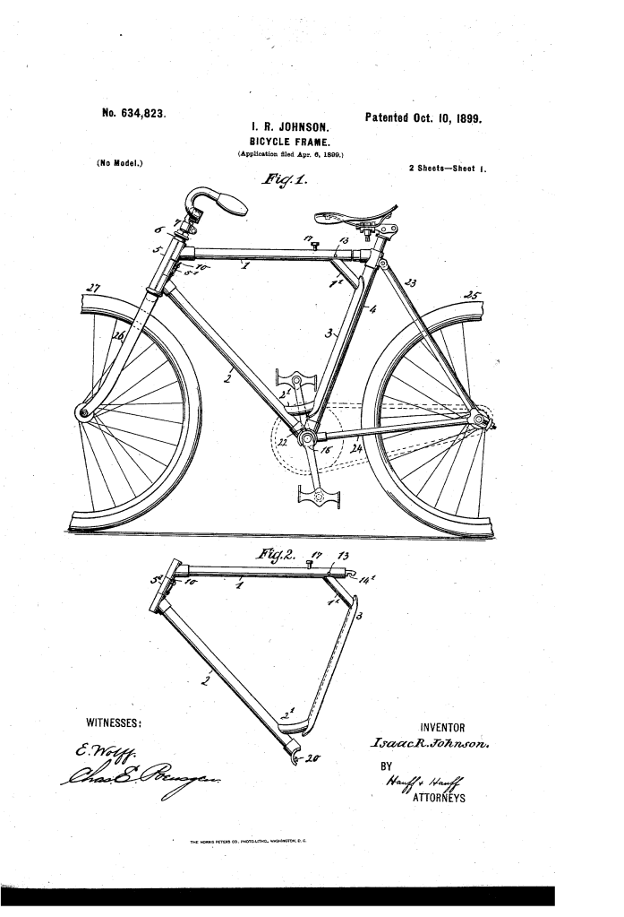
- The Steering Head and Front-Wheel Assembly: Comprising the fork (26), front steering wheel (27), handlebar post (7), and outer steering-post sleeve (6).
- The Removable Central Frame (Diamond): Formed by the upper tube (1), lower tube (2), and a rear curved sheath (3) attached via short joining tubes (1′ and 2′).
- The Rear-Wheel Frame: Formed by the seat-post tube (4), crank-hanger casing (18), and rear stays/branches (23, 24) supporting the rear drive wheel (25).
Johnson’s breakthrough was pairing keyed wedge slots with internal locking pins, allowing the rider to decouple the frame sections in seconds by hand while preventing road vibration from knocking the components loose.
How the Dismountable Frame Functions
The breakdown of the frame follows a two-stage disassembly sequence:
| Step | Action | Mechanical & Safety Purpose |
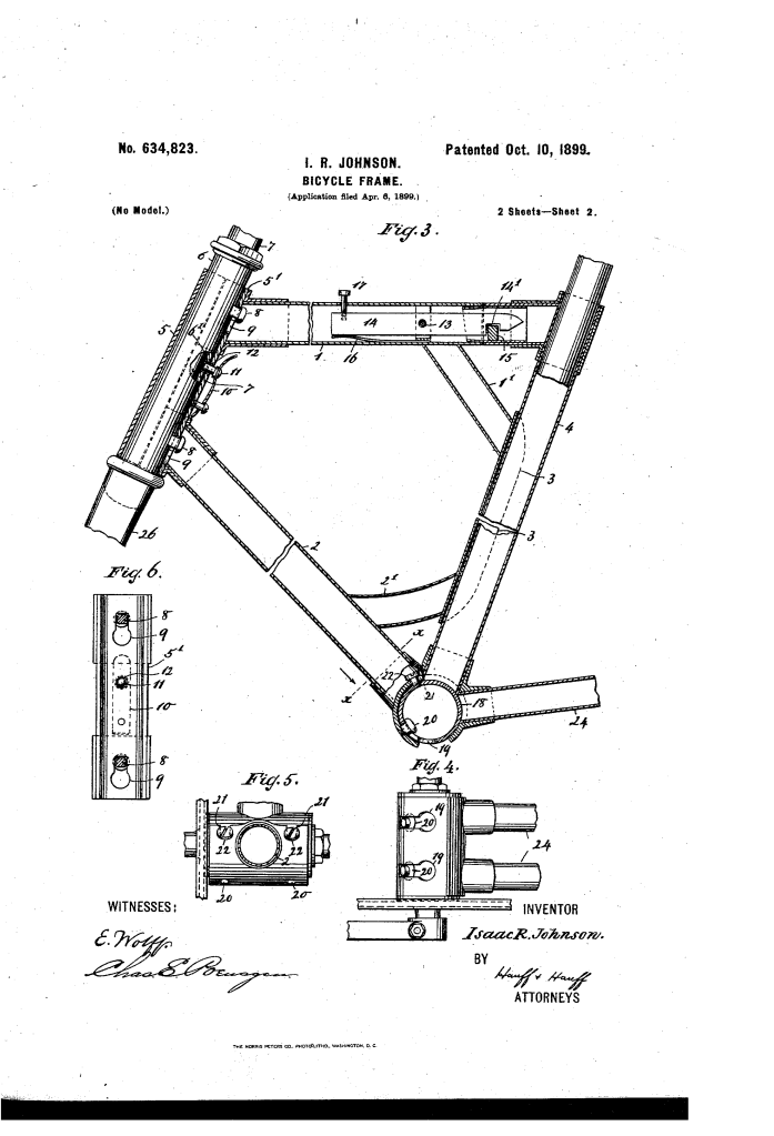
| 1. Disengaging Steering Head | Retract spring pin (11) from alignment apertures (12, 6′) and lift the front diamond frame slightly. | Disengages the lock and lets headed studs (8) slide out through the enlarged ends of keyhole slots (9). |
| 2. Detaching Upper Tube | Depress external push button (17) on the upper tube (1). | Tilts internal lever (14) against spring (16) around fulcrum (13), lifting catch recess (14′) off internal locking lug (15). |
| 3. Revolving Central Diamond | Pivot the diamond frame slightly downward around the bottom crank-hanger sleeve (18). | Guides headed studs (20) out of the narrow track into the wide portion of keyhole slots (19). |
| 4. Full Separation | Slide lower tube (2) off crank-hanger guide studs (22) via steadying slots (21). | Separates the center frame from the rear-wheel drive assembly for compact packing. |
Key Mechanical Components
- Keyhole Slot-and-Stud Connectors (8, 9, 19, 20): Headed studs slide into wide aperture openings and seat securely in narrowed channels. The overlapping stud heads clamp the frame sections flush against lateral and torsional stress.
- Spring-Loaded Locking Pin (10, 11): A leaf spring mounted to the front head sheath (5′) forces pin (11) through registered holes in the steering sleeve to prevent riding vibration from dislodging keyhole joints.
- Fulcrum Rocker Lever & Push Button (13, 14, 17): Housed inside upper tube (1), this concealed rocker mechanism provides positive retention across the top tube without exterior clamping hardware.
- Crank-Hanger Steadying Guides (21, 22): Auxiliary slots and alignment studs fitted to the bottom bracket ensure frame alignment under pedaling torque.
- Dust Guards: Spring-hinged aperture covers automatically seal open keyhole slots (19) when assembled, blocking road grit from entering the bottom bracket bearings and pedal spindle.
Versatility and Industrial Application
While illustrated using a standard men’s diamond frame, Johnson explicitly designed the system for broad adaptation:
- Drop Frames & Velocipedes: The joint configuration accommodates open step-through (“drop”) frames for women’s bicycles, tricycles, and four-wheeled velocipedes.
- Intermodal Transit: Enabled commuters to store bicycles in small apartment closets, building elevators, vehicle trunks, and passenger rail compartments without removing oily drive chains or mechanical pedals.
About the Inventor: Isaac R. Johnson
Isaac R. Johnson was an African American inventor living and working in Manhattan, New York, during the late 19th and early 20th centuries. His work on Patent No. 634,823 reflected the technical ambition of urban inventors during the peak of the American bicycle craze, creating mechanical solutions that bridged personal mobility with compact municipal transit.
Summary of Claims
The patent explicitly claims:
- A bicycle frame featuring separable front and rear tubular sheaths detachably joined to a steering-post sleeve and seat-post tube.
- The combination of a crank-hanger frame, a detachable secondary frame, a slot-and-stud locking interface, and an upper tube retaining catch.
- The integration of steadying guide slots (21) and studs (22) to lock the lower tube rigidly against the crank hanger under driving loads.
- A spring-actuated lock pin (11) configured to maintain positive engagement between the steering head and central frame against road vibration.
