
Automatic Telephone Alarm Apparatus (1970)
U.S. Patent No. 3,505,476, granted on April 7, 1970, to Lawrence Randolph Kelly, Jr., and Clyde Edward Gurley (assigned to Pelass Systems, Inc.), addresses a major limitation in emergency response infrastructure: automatically contacting public emergency services during crimes or fires without depending on third-party monitoring bureaus or making illegal hardwired splices into telephone company wiring.
During the late 1960s, commercial security installations typically required dedicated leased telegraph lines or third-party dispatch agencies, which were costly and introduced human dispatch delays. Direct-dial electronic equipment, meanwhile, violated strict utility regulations prohibiting unauthorized physical taps into subscriber lines. Kelly and Gurley, based in Washington, D.C., developed the Programmable External Lifting Automatic Sequential Selecting System (PELASSS)—an electromechanical apparatus operating completely external to the telephone instrument and line, capable of physical handset lifting, acoustic tone recognition, mechanical dialing, and automated redialing during busy signals.
The Core Design: The Completely External Telephone Interface
The distinguishing characteristic of the Kelly and Gurley apparatus is its 100% external, non-invasive architecture. It interacts with standard rotary dial or push-button telephone sets exactly as a human operator would, utilizing physical actuation and acoustic coupling.
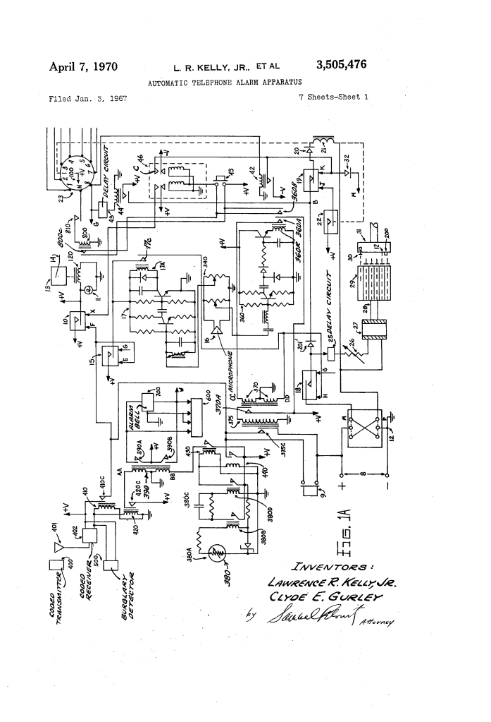
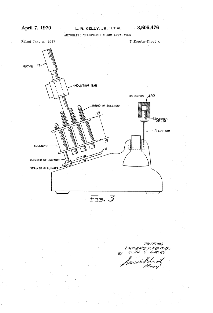
- Solenoid Handset Lift Mechanism (120, 13, 14)
- A high-force lifting solenoid (120) drives a vertical plunger (13) coupled to an external lift arm (14).
- Upon alarm triggering, the arm physically hoists the handset off the cradle switches to seize the telephone line and await the central exchange dial tone.
- Acoustic Discriminator & Tuned Filtering (16, 340, 17, 360)
- An external acoustic microphone (16) rests adjacent to the telephone receiver earpiece.
- A tuned amplifier (17) filters specifically for the standard dial tone frequency; its presence triggers the main sequencing switch (18).
- An integrated count-integrator amplifier (360) continuously samples receiver audio to distinguish between a standard ringing signal and the faster repetition rate of a busy signal.
- Motorized Mechanical Rotary Dialing Assembly (27, 28, 29)
- A circular mounting plate (29) carries ten discrete plungers driven by solenoids (24, 33–41) positioned directly above the digit holes of the rotary wheel (31).
- A reversible DC motor and gear drive (27) oscillates the carrier assembly clockwise until the extended plunger impacts a mechanical stop (200) and flips limit switch 12, after which the motor reverses to the rest position to advance an electromechanical stepping switch (23).
How the Apparatus Functions
The system executes a strictly coordinated mechanical and acoustic cycle from initial trigger to recorded report:
| Step | Action | Functional Purpose |
| 1. Event Detection | A panic transmitter (400), sensor (500), or thermistor (380) activates relay 410. | Energizes handset solenoid 120, physically lifting receiver to draw a dial tone. |
| 2. Dial Tone Sensing | Microphone 16 picks up the tone, driving tuned amplifier 17 to close relay 18. | Verifies line availability before dialing begins, preventing premature dialing pulses. |
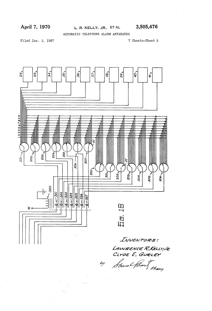
| 3. Digit Execution | Stepping switch 23 routes power to the solenoid selected by rotary switch 201. | The chosen solenoid inserts its plunger into dial hole 1; motor 27 rotates the wheel to stop 200. |
| 4. Step Progression | Striker impacts limit switch 12, reversing motor 27 and indexing stepping switch 23. | Resets the disc to rest and fires the next digit solenoid in sequence until all 7 digits are dialed. |
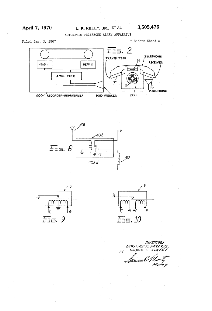
| 5. Message Transmission | Multi-channel reproducer 600 plays through an acoustic coupler into mouthpiece T. | Broadcasts a recorded emergency message directly to emergency dispatchers. |
| 6. Busy-Line Recycling | If a busy signal is detected by count-integrator 360, solenoid 120 drops the handset. | Hangs up the line, pauses for time-delay relay 375, hoists the receiver, and redials automatically. |
Technical Components
| Component | Function |
| Lifting Solenoid (120) & Arm (14) | Mechanically lifts the telephone receiver from the cradle to open the line circuit. |
| Acoustic Microphone (16) & Mixer (340) | Listens to earpiece tones without making electrical contact with telephone wiring. |
| Tuned Dial-Tone Amplifier (17) | Bandpass amplifier responsive strictly to central exchange dial-tone frequencies. |
| Count-Integrator Amplifier (360) | High-speed pulse discriminator tuned to detect the repetition frequency of busy signals. |
| Stepping Switch (23) & Wiper Arm (100) | Multi-position rotary stepping mechanism that cycles through digits 1 through 7. |
| Digit Setting Switches (201–207 / 300–306) | Manual 10-position rotary selectors used to program police, fire, or personal contact numbers. |
| Reversible DC Motor & Gear Drive (27) | Provides mechanical torque to oscillate the dialing head assembly against stop 200. |
| Multi-Channel Tape Reproducer (600) | Stores independent prerecorded voice announcements (e.g., robbery on Channel 1, fire on Channel 2). |
| Push-Button Adapter Disc (220) | Slotted sector plate replacing the rotary gear drive to adapt the unit directly to DTMF keypad consoles. |
Historical and Technical Impact
The PELASSS system by Kelly and Gurley addressed key legal and structural challenges during the transition to automated security infrastructure:
- Regulatory Compliance: Under pre-Carterfone and early post-Carterfone telecommunications tariffs, connecting hardwired foreign attachments directly to telephone lines was heavily restricted. By functioning entirely externally via physical movement and acoustic coupling, the apparatus bypassed regulatory and warranty violations.
- Direct Action Notification: Most contemporary systems routed calls to private detective or central monitoring agencies, causing operational bottlenecks. PELASSS dialed municipal police desks or fire dispatchers directly in real time.
- Automated Persistence: The busy-line sensing and automated mechanical redial capability ensured messages reached emergency services during widespread crises or network congestion.
About the Inventors: Lawrence R. Kelly, Jr. & Clyde E. Gurley
Lawrence Randolph Kelly, Jr., and Clyde Edward Gurley were African American inventors and systems designers based in Washington, D.C., who founded Pelass Systems, Inc.
- Systems Engineering: Kelly and Gurley developed automated communications interfaces, electromechanical actuators, and early automated dialing frameworks, patenting foundational sequential logic controllers designed for commercial and residential safety.
- Technological Transition: Their design anticipated modern autodialing and digital home monitoring architectures, providing automated emergency dispatch through electromechanical logic before low-cost microprocessors and registered direct-connect modular jacks were established.
Summary of Claims
The patent explicitly claims:
- An automatic telephone communication apparatus responsive to predetermined emergency events, operating completely external to the telephone instrument and line.
- A solenoid-actuated mechanical lifter configured to physically displace a telephone receiver off its cradle hook switch upon sensor trigger.
- Discriminating acoustic circuitry that senses audible dial tones to initiate dialing pulses and distinguishes busy tone frequencies to initiate an automatic hang-up and redial sequence.
- A stepping switch synchronized with a bank of preset multi-position switches to sequentially energize external dialing plungers corresponding to programmed telephone numbers.
- A multi-channel audio reproducing device configured to acoustically transmit distinct prerecorded spoken alarms directly into the telephone transmitter mouthpiece.
