

Automatic Safety Brake System (1962)
U.S. Patent No. 3,015,522, granted on January 2, 1962, to Richard B. Spikes, describes a fail-safe hydraulic braking system for vehicles. While modern cars use “split” hydraulic circuits (front/rear or diagonal) to provide backup, Spikes’ invention proposed a complete primary and auxiliary (reserve) hydraulic system that automatically switches over if the main system fails due to a leak or pressure loss.
The Core Problem: Hydraulic Failure
In a standard 1950s hydraulic brake system, a single leak in a wheel cylinder or a ruptured brake line could lead to a total loss of braking power. Earlier “dual” systems often relied on mechanical cables as a backup, but these were bulky and lacked the stopping power of hydraulics. Spikes sought to create a system where the backup was just as powerful as the primary.
How the System Works
The Spikes system utilizes a “sensing” mechanism to detect when the primary system has lost fluid and instantly redirects hydraulic pressure to a secondary set of actuators.
1. Dual-Acting Actuators
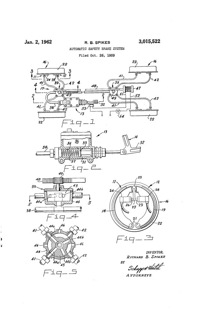
At each wheel, instead of a single cylinder pushing the brake shoes, Spikes designed a dual-cylinder setup:
- Primary Cylinder (24): Operates under normal conditions.
- Auxiliary Cylinder (28): Remains idle until a failure occurs.
- The Cam (23): Both cylinders act on the same lever arm connected to a cam. Rotating the cam in either direction spreads the brake shoes against the drum. If the primary cylinder fails, the auxiliary cylinder simply rotates the cam in the opposite direction to achieve the same braking force.
2. The Automatic Transition (The Sensing Means)
The switch from primary to auxiliary is handled by an electrical and hydraulic “brain”:
- Master Cylinder Piston (33): The master cylinder is designed with extra length. In a healthy system, the piston only travels halfway. If a leak occurs, the pedal sinks lower.
- Safety Switch (53): When the brake pedal/piston moves past a “predetermined point” (indicating a loss of fluid), it hits a switch.
- Solenoid and Valve (47, 39): The switch activates a solenoid that moves a rack-and-pinion gear. This rotates a two-way valve, instantly cutting off the leaky primary lines and opening the path to the auxiliary lines.
Key Features and Safety Signals
Spikes included several features to ensure the driver remained informed of the vehicle’s status:
- Equal Efficiency: Because the primary and auxiliary cylinders are the same size, the driver doesn’t lose stopping power during a failure.
- Tactile Signal: As the valve switches, the brake cam swings from one side to the other. This creates a “tiny instant” of release that the driver can feel through the pedal—a physical “thump” signaling that the primary system has failed.
- Visual Signal: A warning light (54) on the dashboard illuminates the moment the reserve system is engaged.
Summary Table: Primary vs. Auxiliary
| Component | Primary System (Normal) | Auxiliary System (Emergency) |
| Hydraulic Lines | Active | Sealed/Inactive |
| Wheel Cylinder | Cylinder 24 (Pushes lever) | Cylinder 28 (Pushes lever) |
| Pedal Position | Upper half of travel | Lower half of travel |
| Trigger | Driver intent | Piston travel past safety switch |
Historical Significance
Richard Spikes was a prolific African American inventor who also held patents for a directional light (turn signal) and an improved gear shift. His work on the safety brake system was a precursor to the redundant braking systems required by law in modern vehicles, prioritizing the idea that a hydraulic failure should not result in a loss of control.
