
Automatic Locking Switch (1898)
U.S. Patent No. 609,436, granted on August 23, 1898, to William H. Jackson, addresses a vital railway safety hazard of the late 19th century: derailments and catastrophic collisions caused by improperly lined, unsecured, or prematurely thrown track switches.
During this era of rapid railroad expansion, trains being shifted onto sidings were vulnerable if a switch was accidentally released or forced back to the main line before all cars cleared the junction. Jackson, an inventor based in Indianapolis, Indiana, engineered a mechanical interlocking and counterweighted track system that locks a switch open to a siding as long as rolling stock occupies the track, returning it automatically to a closed, clear main line only after the entire train has passed safely through.
The Core Design: The Trip-Rail and Interlocking Mechanism
The core of Jackson’s apparatus is an integrated, weight-actuated safety cycle that ties the mechanical position of the switch directly to the physical presence of train wheels on the siding.
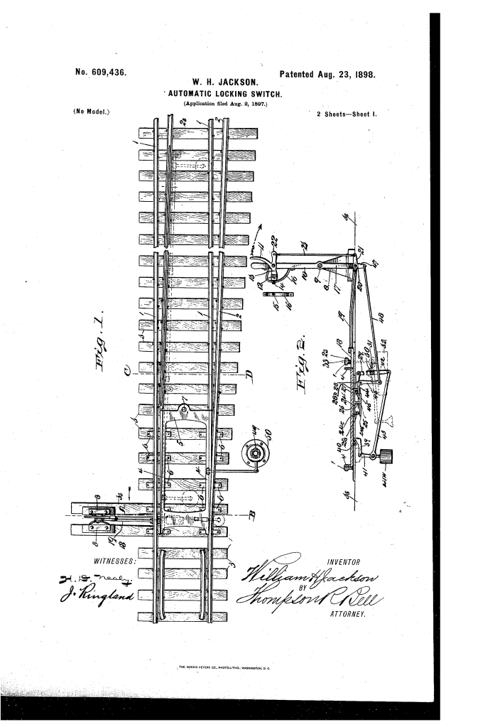
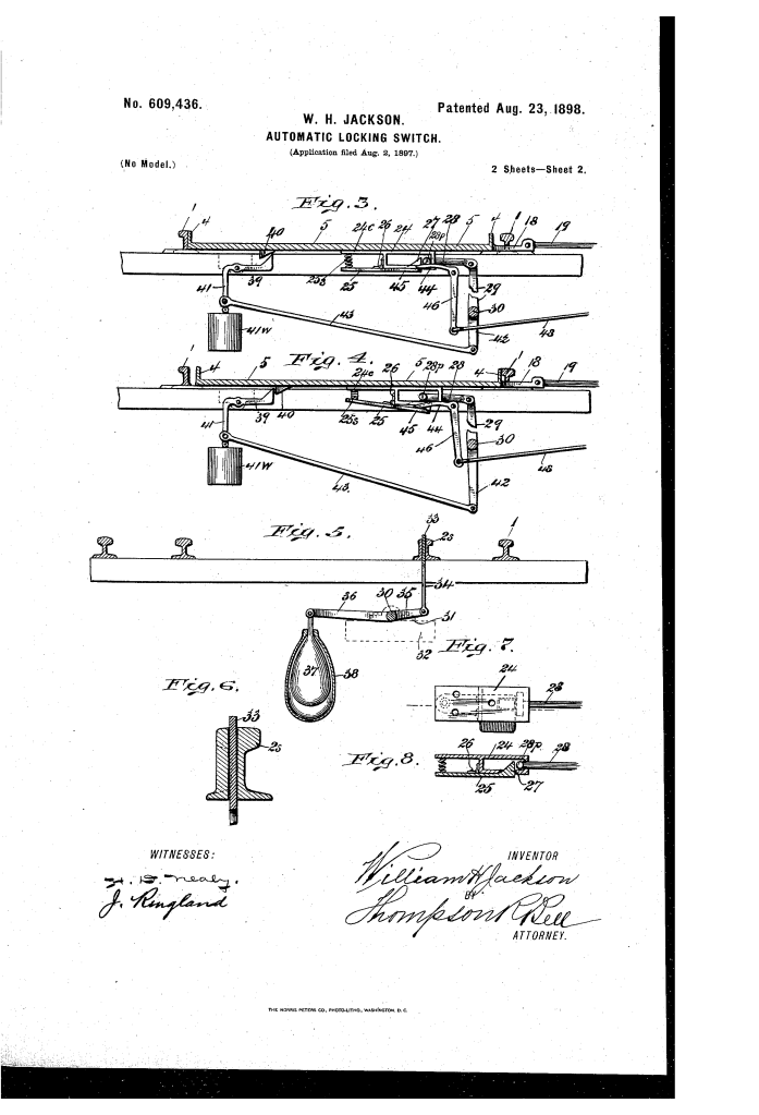
- The Slotted Siding Rail and Trip-Rail (2′, 33)The primary sensor of the system is a vertically mobile trip-rail (33) fitted directly inside a longitudinally slotted, thickened rail web (2′) on the siding track.
- While unloaded, counterweights hold this trip-rail elevated above the running surface of the rail.
- When a train moves onto the siding, the heavy wheel flanges ride over the trip-rail, forcing it downward into the slot and holding it depressed through mechanical weight alone.
- The Counterweighted Rocker Shaft (30, 37)Beneath the railroad ties, Jackson mounted a heavy-duty counterweight shaft (30) set in secure journal bearings (31).
- Connecting rods (34) link the trip-rail directly to levers (35) keyed to this central shaft.
- Opposing levers (36) suspend heavy counterweights (37) housed inside sub-surface protective casings (38) embedded in the ground, generating constant gravitational resetting force.
- Interlocking Latch and Retaining Levers (25, 28, 39, 40)To prevent accidental shifting while a train is split across the switch:
- When the switch is initially thrown open to the siding, a bell-crank locking arm (39) engages a stop tooth (40) on the underside of the movable switch-rail plate (5).
- Depressing the trip-rail rotates shaft 30, shifting pawl 28 into contact with spring-loaded latch 25 (tooth 27), simultaneously dropping arm 39 out of the retaining stop so the gravitational reset can trigger the instant the last wheel leaves the trip-rail.
How the Switch Operates
The mechanism follows a synchronized manual-to-automatic sequence:
| Step | Action | Safety Purpose |
| 1. Key Unlocking | Switchman unlocks spring-lock bolt 14 from notched segment 16 on the stand. | Prevents unauthorized tampering or accidental throwing of the main switch. |
| 2. Manual Throw | Operator squeezes latch-lever 11 while pulling switch-lever 10. | Linkage (23, 48, 44) depresses latch 25, freeing pawl 28 and sliding switch-plate 5 open to siding 2. |
| 3. Lock-to-Siding | Locking arm 39 engages tooth 40 beneath switch-plate 5; signal lamp 49 rotates. | Mechanically holds the rails aligned to the siding and alerts approaching traffic visually. |
| 4. Train Passage | Rolling stock wheels depress trip-rail 33; shaft 30 rotates and primes pawl 28. | Keeps the switch completely locked open; prevents manual or accidental resetting while cars span the junction. |
| 5. Automatic Reset | Last car clears trip-rail 33; counterweights 37 drop by gravity. | Rotates shaft 30, driving pawl 28 to pull switch-plate 5 automatically back to the clear main track. |
Technical Components
- Switch-Rail Plate (5): A rigid platform resting on bearing plates (6) and pivoted at pin 7 intermediate to the main rails, ensuring switch-rails 4 maintain exact track gauge while pivoting.
- Enclosed Latch Case (24): A protective housing shielding latch 25 and spring 25′ from packed dirt, gravel, and snow accumulation.
- Differential Arm Linkage (41, 42): Arm 42 is shorter than depending arm 41, moderating the speed of arm 39 so it does not falsely catch stop tooth 40 during high-speed automatic resetting.
- Sub-Surface Casings (38): Pit housings sunk into the ground ballast to give counterweights 37 unrestricted vertical travel free from track debris.
Historical and Industrial Impact
William H. Jackson’s automatic locking switch contributed to the crucial transition from fallible human labor to fail-safe mechanical automation in late-19th-century railroading.
- Human Error Mitigation: Switchmen frequently faced severe weather, long hours, and poor visibility. By automating the closure sequence, Jackson eliminated the risk of an exhausted or distracted operator leaving an open switch behind a departed train.
- Elimination of Mid-Train Derailments: In standard yards, prematurely realigning a switch while a long freight train was mid-transit split the train across two tracks, causing immediate derailments and yard blockages. The physical depression of trip-rail 33 made mid-train shifting mechanically impossible.
- Durability Under Yard Conditions: By housing key springs, latches, and swinging counterweights in enclosed subterranean cases, the apparatus addressed the harsh winter ice, snow, and grit that routinely disabled early pneumatic and mechanical interlocking equipment.
About the Inventor: William H. Jackson
William H. Jackson was an inventor active in Indianapolis, Indiana, during the height of the industrial railroad era. Collaborating locally with Willis F. Martin, Jackson developed and patented targeted mechanical solutions that tackled foundational railroad infrastructure problems, focusing his engineering efforts on track bed safety, mechanical linkage automation, and interlocking junction reliability.
Summary of Claims
The patent explicitly claims:
- A pivoted switch-rail plate (5) operating between tracks, governed by a trip-rail (33) moving vertically inside a longitudinally slotted siding rail (2′).
- A subterranean rock shaft (30) combining counterweight levers (36, 37) with trip-rail connecting linkages (34, 35) to drive an automatic reset pawl (28).
- An interlocking latch mechanism that mechanically locks the switch-rail plate in siding alignment as long as car wheels depress the trip-rail, releasing and automatically throwing the switch back to the main track once pressure is removed.
