
Automatic Discharge Valve (Crosthwait & Brennan, No. 1,871,044)
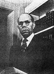
This 1932 patent, developed by David N. Crosthwait, Jr. and Harry Brennan, introduces a sophisticated “quick-acting power-operated discharge valve.” Crosthwait, an influential African American inventor and engineer, designed this specifically for sub-atmospheric vacuum steam heating systems.
The primary problem it solves is the failure of standard valves in pumping systems. In these systems, valves often open and close too slowly, leading to “wire-drawing” (erosion of the valve seat) or the accumulation of sediment that prevents a tight seal. This invention uses a diaphragm motor and a snap-action pilot valve to ensure the main valve opens and closes instantly and forcefully.
1. The Pumping System Context
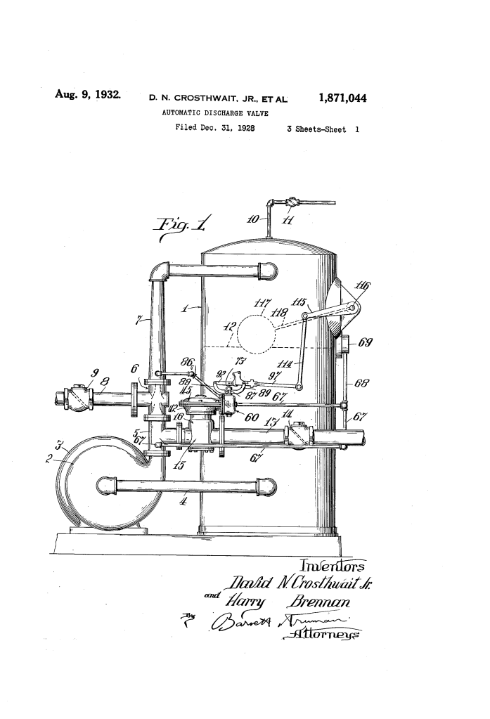
The valve is part of a “hurling circuit” (a water-in-motion vacuum pump).
- The Tank (1): Collects condensate and air from a heating system.
- The Pump (2): Maintains a vacuum to pull in more condensate.
- The Discharge (13): When water in the tank reaches a certain level, it must be forced back into the boiler against high pressure. The Automatic Discharge Valve (15) controls this return flow.
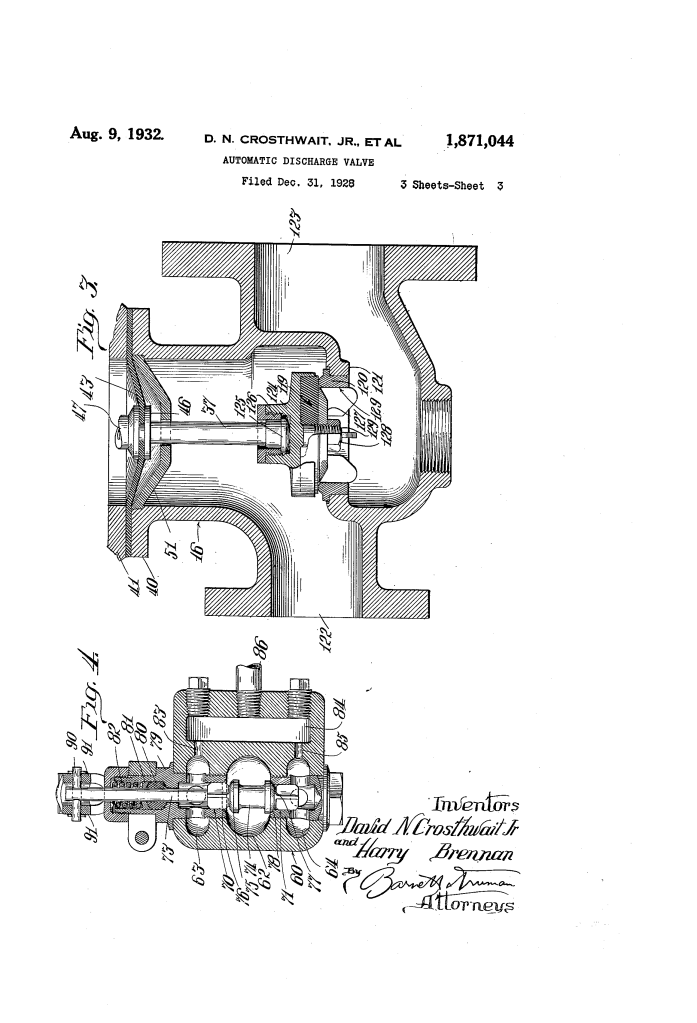
2. The Main Double-Valve Construction
Inside the main housing (16), the inventors utilized a unique double-valve design to prevent “water hammer” and ensure a perfect seal.
- Opposed Disks (24, 25): Two flexible composition disks are mounted on a toggle link (33).
- The Toggle Action: When the valve stem (37) moves down, the toggle link straightens, pushing both disks simultaneously against their seats (20, 21).
- Reservoir Effect: This design creates a small chamber between the valves that cushions the flow as it shuts, preventing the loud banging (water hammer) common in high-pressure plumbing.
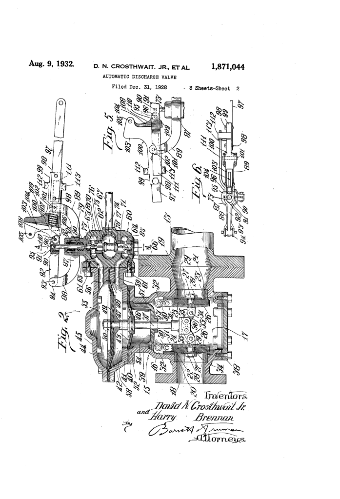
3. The Diaphragm Motor
The valve is not operated by a handle, but by a “motor” powered by water pressure from the system itself.
- Dual Diaphragms (43, 44): The valve stem is attached to flexible rubber or metal sheets called diaphragms.
- Pressure Chambers: By forcing water into the upper chamber (55) or the lower chamber (58), the system creates a massive pressure differential that slams the valve stem up or down.
4. The Snap-Action Pilot Valve
To control the large diaphragm motor, the system uses a smaller Pilot Valve (60). Because the water level in the tank rises slowly, a normal valve would open slowly. The inventors added a “snap-action” mechanism to ensure it only moves when it is ready to move completely.
- Float Actuator (117): A float in the tank moves a lever (97) as the water rises.
- Cam and Roller (104, 95): The lever compresses a spring (106) against a peaked cam.
- The Snap: As the float reaches a set height, the roller slips over the peak of the cam. The stored spring energy “snaps” the pilot valve stem (73) into the new position instantly. This redirects the high-pressure water to the main diaphragm, opening the discharge valve at full speed.
5. Technical Component Summary
| Component | Function |
| Pilot Valve (60) | Controls the flow of high-pressure water to the diaphragm motor. |
| Restricted Outlets (83, 85) | Constantly bleed a small amount of water to ensure pressure doesn’t build up accidentally from minor leaks. |
| Composition Disks (24, 25) | Flexible valve faces that can seal tightly even if small particles are present. |
| Fingers (112, 113) | Safety feature; if the “snap” spring fails, these physical tabs force the valve to move manually. |
Engineering Significance
Crosthwait’s design transformed heating maintenance. By using system pressure as the source of power, the valve doesn’t require an external motor or electricity to operate. The “snap-action” prevented the erosion of valve seats, which previously required constant, expensive repairs in large-scale buildings.
