
Apparatus for Washing Vehicles (1897)
U.S. Patent No. 579,242, granted on March 23, 1897, to William Henry Phelps, describes an overhead swinging pipe apparatus equipped with a specialized leak-resistant swivel joint designed for washing carriages and wagons in stables and carriage houses. Phelps, an inventor residing in Indianapolis, Indiana, developed a mechanism to streamline vehicle cleaning and eliminate the wear, entanglement, and overhead leakage common to early wash setups.
Prior to this invention, vehicle washers dragged long hoses across dirty stable floors, risking hose damage, vehicle scratching, and poor mobility. Phelps’s system suspended the wash hose overhead on a track, allowing it to glide effortlessly 360 degrees around a stationary vehicle.
The Core Design: The Overhead Swivel and Track Assembly
The core innovation of the Phelps system is the combination of an overhead circular track with a spring-tensioned, ball-bearing swivel joint. This allows water to flow continuously from a fixed supply line into a swinging boom pipe without dripping on the operator or vehicle below.
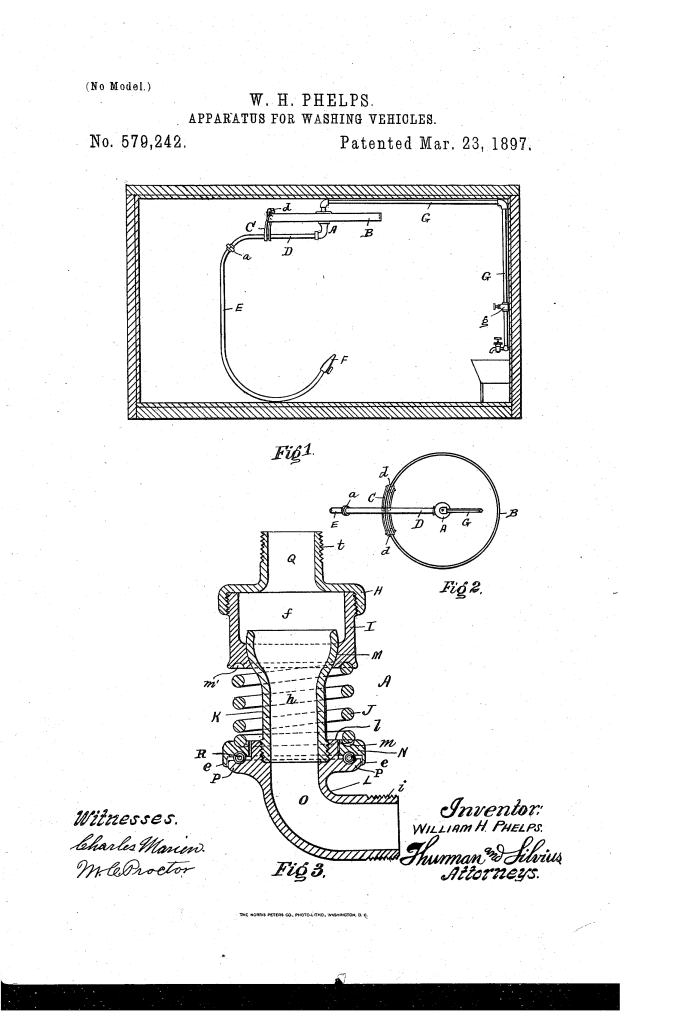
- The Leak-Resistant Swivel Joint (A)The swivel joint solves the common failure of rotating water fittings by combining ball bearings with a spherical ball-and-socket seal.
- Non-Corrosive Construction: Fabricated preferably from composition brass to prevent rust and degradation from constant water exposure.
- Ball-and-Socket Seating (M): A cup-shaped casing (I) receives a ball-shaped swivel piece (K) to form a sealed spherical joint.
- Dual Support Mechanism: An internal spring (J) maintains constant pressure on a floating collar (N), while ball bearings (R) seated in annular grooves reduce friction between the collar and the lower elbow flange (P).
- The Overhead Track and Carriage (B, C)To prevent sagging and reduce mechanical stress on the center joint:
- A circular track (B) is suspended directly beneath the ceiling above the vehicle wash bay.
- A wheeled carriage (C) fitted with rollers (d) travels along the track, supporting the outer end of the swinging pipe arm (D).
How the Apparatus Functions
The apparatus simplifies the vehicle washing sequence while keeping work areas clear:
| Step | Action | Practical Purpose |
| 1. Water Delivery | The overhead supply valve (g) is opened, routing pressurized water into supply pipe (G) and through central passage (Q, f, h, O). | Supplies continuous water flow directly overhead without floor obstruction. |
| 2. Circular Traversal | The operator holds nozzle (F) and walks around the carriage; the hose pulls pipe arm (D) along track (B). | Keeps the hose elevated and prevents it from rubbing against or scratching the vehicle’s paint. |
| 3. Swivel Rotation | Joint (A) rotates smoothly on ball bearings (R) while spring (J) holds joint (M) sealed tight against water pressure. | Prevents water from leaking or dripping down onto the operator or clean vehicle. |
| 4. Vehicle Clearance | After washing, the pipe and short drop hose (E) are pushed to one side of the bay. | Allows the vehicle to exit immediately without stopping to manually coil and store hoses. |
Key Technical Components
- Swivel Joint Assembly (A): Comprises top nipple connection (H), threaded cup body (I), swivel piece (K), spring (J), loose collar (N), and rotating elbow (L).
- Overhead Carriage (C): Houses rollers (d) that glide along track (B) to support the weight of the cantilevered swinging pipe (D).
- Drop Hose & Nozzle (E, F): Connected via coupling (a) to the bent outer end of pipe (D), providing direct, flexible handling at vehicle height.
Practical and Operational Advantages
- Overhead Clearance: Eliminates tangled hoses on the floor, extending hose longevity and keeping the wash area free of tripping hazards.
- Leak Prevention: The integration of ball bearings and spring-loaded spherical seating prevents overhead dripping—a frequent defect in early plumbing swivel joints.
- Labor Efficiency: Allows a single stable hand or detailer to move rapidly around the entire perimeter of a carriage without stopping to reposition equipment.
About the Inventor: William Henry Phelps
William Henry Phelps was an Indianapolis, Indiana-based inventor working during the height of the late-19th-century carriage manufacturing era. His mechanical design reflected the growing demand for dedicated, efficient maintenance infrastructure in municipal livery stables, commercial carriage houses, and early fleet operations.
Summary of Claims
The patent explicitly claims:
- The combination within a vehicle washing apparatus of a swivel pipe joint comprising top fitting H and cup-shaped casing I connected via screw threads.
- A spherical ball-and-socket joint formed between cup I and rotating swivel piece K.
- Elbow L featuring flange P threaded to swivel piece K.
- Collar N with annular grooves on upper and lower surfaces, housing spring J between cup I and collar N.
- Ball bearings R seated in matched annular grooves between collar N and flange P to ensure smooth rotation under fluid pressure.
