
Antenna Testing Shield (1962)
U.S. Patent No. 3,029,430, granted on April 10, 1962, to Howard S. Jones, Jr., and assigned to the United States Army, describes a specialized “space hood” designed to test microwave fuzes for guided missiles. The invention solved a critical Cold War-era engineering challenge: how to test a missile’s radar-based proximity fuze on a laboratory bench while tricking the electronics into thinking they are flying through the vacuum of free space.
The Engineering Challenge: Simulating Free Space
Guided missile fuzes use microwave antennas to sense when they are near a target. Testing these fuzes in a standard laboratory is difficult because:
- Antenna Leakage: Signals from the missile’s own transmitter can leak directly into its receiver, causing “blinding.”
- Skin Currents: Radio frequency (RF) energy travels along the metallic “skin” of the missile, creating interference.
- Reflection: In a normal room, microwave signals bounce off walls and metal objects, creating false targets.
Previous testing methods couldn’t effectively isolate these factors. Jones’s invention created a controlled, shielded environment that simulates the “quiet” of free space.
How the Testing Shield Works
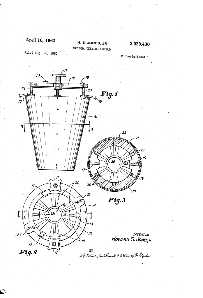
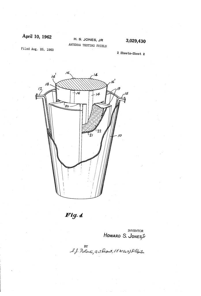
The device is a conical metallic hood (10) that fits snugly over the nose of a missile fuze (18). Its effectiveness comes from its internal compartmentalization.
1. Isolated Compartments
The interior of the hood is divided by conductive partitions (19). When the fuze is inserted, these partitions align with the fuze’s surface.
- Metallic Strips (20): Made of springy beryllium-copper, these strips press against the fuze skin to ensure an electrical seal.
- Isolation: Each individual antenna on the fuze is “trapped” in its own private chamber, preventing signals from jumping between antennas along the missile’s surface.
2. Microwave Absorption
To prevent internal reflections (echoes), the chambers are heavily treated:
- Current Absorbing Material (21): Lines the walls to soak up surface currents.
- Microwave Absorbing Material (22): Fills all compartments that do not contain active test antennas, effectively creating a “black hole” for RF energy.
3. The Coupling Loop
Only two compartments are active. One contains a hood receiving antenna (17) and the other contains a hood transmitting antenna (15).
- The fuze’s transmitter sends a signal to the hood’s receiver (17).
- This signal is sent to external test equipment that simulates a target (adding delay and Doppler shift).
- The modified signal is sent back through the hood’s transmitter (15) to the fuze’s receiver (16).
Technical Performance
| Feature | Performance/Value |
| Decoupling | Up to 60 dB isolation between adjacent antennas |
| Noise Reduction | 8-fold reduction in receiver noise compared to prior art |
| Optimal Spacing | ~1.75 inches between fuze and hood antennas |
| Materials | Beryllium-copper contact strips; RF-absorbing foam/liners |
Significance of the Invention
By providing a “portable free space,” this shield allowed engineers to run thousands of simulated flights without ever launching an expensive missile. It ensured that proximity fuzes would trigger exactly when they were supposed to, rather than being confused by their own internal reflections or laboratory interference.
