
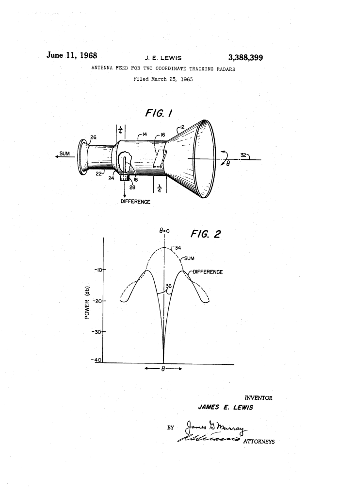
Antenna Feed for Two Coordinate Tracking Radars (1968)
U.S. Patent No. 3,388,399, granted on June 11, 1968, to James E. Lewis, describes a streamlined microwave antenna feed designed to extract simultaneous range and angle tracking data using circular waveguides. James E. Lewis, an engineer based in Washington, D.C., assigned the patent to the United States of America as represented by the Secretary of the Navy.
This specific invention solved a persistent hardware and performance problem in two-coordinate radar tracking: older systems relied on bulky dual-rectangular-horn arrangements linked to complex microwave hybrids (such as rat-race rings or magic-T junctions) to produce sum and difference tracking signals. These rectangular feed networks introduced excessive weight, mechanical complexity, and polarization tracking limitations. Lewis developed a compact, circularly symmetric waveguide feed that extracts range information in one propagation mode and off-axis angle tracking in another mode without requiring external hybrid junctions.
The Innovation: Dual-Mode Circular Waveguide Tracking
Radar tracking requires two distinct informational channels: a “sum” signal (maximum when aimed directly on-target for distance ranging) and a “difference” signal (nulled when on-target and increasing sharply off-axis for angular correction).
Lewis solved this by exploiting the modal cutoff properties of circular waveguides. Instead of splitting signals through external plumbing, he designed a tiered circular assembly where the physical diameters of the waveguide sections dictate which electromagnetic modes can propagate:
- Ranging Mode (TE11): The fundamental transverse electric mode travels through both large and small circular sections to supply the range (sum) signal.
- Angle Mode (TM01): Asymmetric, off-axis target reflections excite the higher-order transverse magnetic mode in the large circular section. Because the downstream transition tapers down below the TM01 cutoff diameter, this mode cannot enter the smaller guide and is reflected as a standing wave to provide the angle (difference) signal.
Why Circular Cross-Sections?
Symmetry: The circular profile eliminates directional polarization biases and provides superior angular tracking resolution in both elevation and azimuth.
Hardware Simplification: It completely eliminates external hybrid junctions, magic-T combiners, and redundant rectangular horn assemblies.
Polarization Versatility: Incorporating a quarter-wave plate converts linear pulses into circular polarization, allowing the antenna to interrogate transponders or radar targets on aircraft and spacecraft regardless of vehicle orientation.
Key Microwave Components
The feed assembly integrates mode-filtering wave sections with decoupled signal extraction probes:
| Component | Schematic Callout | Function |
| Conical Horn | 12 | Flared circular radiator that electromagnetically couples microwave energy between the waveguide assembly and free space (or a reflector dish). |
| Large Circular Waveguide | 14 | Sized to support both the dominant TE11 mode and the higher-order TM01 tracking mode. |
| Quarter-Wave Plate | 16 | Optional dielectric or phase-shifting insert that converts linear polarization to circular polarization for aspect-independent vehicle tracking. |
| Angle Coupling Probe | 18 | Capacitive probe positioned roughly one-quarter wavelength from the tapered throat to extract the radially symmetric TM01 difference signal. |
| Tapered Waveguide Section | 24 | Funnel section joining the two guides; acts as an electrical cutoff short that reflects TM01 energy while passing TE11 waves. |
| Small Circular Waveguide | 22 | Constricted guide dimensioned to propagate TE11 energy while remaining beyond cutoff for the TM01 mode. |
| Mechanical Coupling Flanges | 26, 28 | Waveguide ports routing the TE11 sum signal (flange 26) and TM01 difference signal (port 28) into radar receiver circuits. |
Performance: Sum and Difference Extraction
The patent provides comparative operational characteristics illustrating how target alignment controls mode propagation:
Operational Response:
On-Axis Target (Theta = 0): Reflected energy returns symmetrically along central axis 32. Only the TE11 mode is excited, producing peak signal amplitude at port 26 (Curve 34) for maximum ranging sensitivity. The TM01 mode remains completely unexcited, creating a deep null at probe 18.
Off-Axis Misalignment (Theta > 0): Non-uniform phase across horn 12 excites the TM01 mode in large waveguide 14 (Curve 36). The amplitude of this signal increases directly with misalignment angle Theta, while its electrical phase indicates which side of the boresight axis the target occupies.
Probe Isolation: Because probe 18 is oriented to decouple from linearly polarized TE11 transmission pulses, the transmitter does not blind or damage the sensitive angle-detection channel.
How the Apparatus Functions
The antenna feed operates through a defined transmission and reception sequence:
| Step | Action | Operational Purpose |
| 1. Transmission | Radar transmitter injects a linearly polarized pulse via coupling flange 26 into small waveguide 22. | Propagates dominant TE11 mode toward the antenna without exciting probe 18. |
| 2. Polarization Option | Pulse traverses large waveguide 14 and optional quarter-wave plate 16. | Converts linear energy into circular polarization to trigger airborne transponders regardless of roll. |
| 3. Target Reflection | Returned echo enters conical horn 12 along propagation axis 32. | Captures reflected microwave energy and feeds it into large guide 14. |
| 4. Sum Channel Extraction | Symmetrical component propagates as TE11 mode through taper 24 and small guide 22 to flange 26. | Supplies the primary high-sensitivity ranging (sum) signal to the radar receiver. |
| 5. Mode Reflection & Gating | Asymmetric component travels as TM01 mode; taper 24 acts as a cutoff short, reflecting the wave back toward probe 18. | TM01 standing wave peaks one-quarter wavelength from taper 24, where probe 18 extracts the angle (difference) signal. |
Technical and Military Impact
Assigned royalty-free for governmental use, James E. Lewis’s patent provided clear practical benefits to Navy fire control and aerospace telemetry:
- Weight Reduction: Eliminating bulky rectangular hybrids and multi-horn feeds substantially reduced top-weight on shipboard tracking masts and airborne radar gimbals.
- High Boresight Precision: Using a sharp TM01 null at Theta = 0 delivered precise angular resolution for naval gunfire directors, missile tracking radars, and instrument landing systems (ILS).
- Spacecraft Interrogation: Transmitting circular polarization allowed military tracking stations to track tumbling satellites or maneuvering high-performance aircraft without signal fade.
About the Inventor: James E. Lewis
James E. Lewis was an electronics engineer and microwave specialist working in Washington, D.C., for the Department of the Navy. Working during the expansion of Cold War radar and missile-defense technologies, Lewis specialized in electromagnetic propagation, antenna feeds, and waveguide network design, developing compact microwave components that simplified shipboard tracking, fire-control instrumentation, and target-acquisition systems.
Summary of Claims
The patent explicitly claims:
- A microwave antenna feed assembly comprising a conical horn, a larger circular waveguide, a smaller circular waveguide, and an interconnecting tapered section dimensioned so that energy propagates in the TE11 mode through all sections, but in the TM01 mode strictly within the larger waveguide.
- Extracting TE11 mode energy through a first coupling element for receiver ranging circuits and extracting TM01 mode energy through a second coupling element for receiver angle circuits.
- Incorporating a capacitive probe in the larger circular waveguide positioned to reject transmit energy while accepting radially symmetric TM01 energy.
- Incorporating a quarter-wave plate in the larger circular waveguide to support circular polarization transmission and reception.
