
Angle Indicator (Oscar R. Cassell, No. 1,038,291)
The patent by Oscar R. Cassell of New York, N.Y., describes an Angle Indicator (Patent No. 1,038,291, 1912). This device was specifically designed for aerial craft—aeroplanes and dirigibles—to automatically indicate and register the flight angles (pitch and roll). Crucially, the instrument was engineered to “lock” at dangerous angles, serving as a flight recorder that would preserve evidence of a craft’s orientation even in the event of an accident.
Inventor Background: Oscar R. Cassell
Oscar Robert Cassell was an African-American inventor and architect who made significant contributions to early aviation technology.1 While many inventors of the era were focused on propulsion or wing shape, Cassell recognized the dire need for instrumentation. Early aviators relied largely on “seat-of-the-pants” flying; Cassell’s indicator provided a scientific way to monitor stability and dangerous tilts. His background in architecture is evident in the precise, modular geometric design of the instrument, which used gravity and ball-bearing movements to achieve high accuracy.
Invention and Mechanism (Simplified)
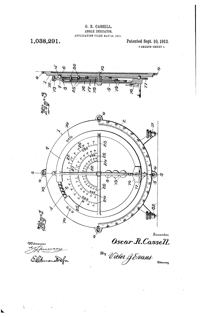
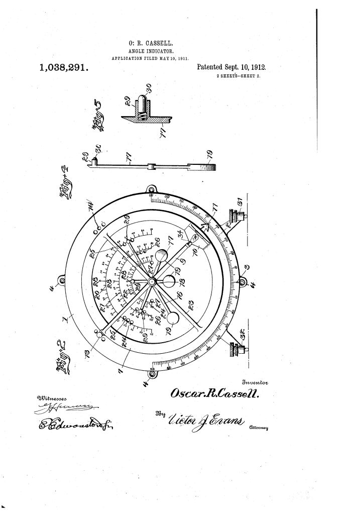
The device consists of a series of nested, weighted pendulums that track movement across 360 degrees.
1. The Pendulum Ring System
- Outer Ring (1) and Inner Ring (7): The outer ring is fixed to the aircraft’s frame via attaching members (4). The inner ring (7) is mounted inside on ball bearings (6), allowing it to rotate freely and stay level regardless of the aircraft’s position.
- Weighted Spoke (9/10): A spoke (9) with a heavy weight (10) at the bottom acts as a master pendulum.
- Function: As the aircraft tilts, the weight keeps the spoke vertical. The pointer (11) moves across the graduations (2) on the outer ring to show the pilot the exact degree of the tilt.
2. The Automatic Locking Mechanism (Key Innovation)
- Spring-Pressed Plunger (12): At the top of the spoke is a plunger (12) that hovers over apertures (14) in the outer ring.
- Function: If the aircraft tilts to a “dangerous angle” (for example, $45^\circ$), the plunger automatically snaps into a hole.
- Result: This locks the inner ring to the outer ring. Even if the plane continues to tumble or eventually crashes, the instrument remains frozen at the specific angle where the danger began, acting like a primitive “black box” data recorder.
3. Secondary and Tertiary Indicators
- Pointers (16, 17, 18): Once the main spoke is locked, a secondary set of weighted pointers (16, 17, 18) begins to move over their own graduated segments (20, 21, 22).
- Function: These pointers track further erratic movements beyond the initial dangerous angle. They also feature plungers to lock in succession at $60^\circ$ and $90^\circ$ intervals.
- Night Use: Cassell included a light (34) mounted on the weight so the pilot could read the scales during night flights.
Concepts Influenced by This Invention
Cassell’s angle indicator influenced the development of flight instrumentation and accident forensic technology.
- The Flight Data Recorder: The concept of an instrument that locks at a critical point to preserve data after a crash is a direct precursor to the modern Flight Data Recorder (FDR).
- Inertial Reference Systems: By using a weighted inner ring on ball bearings to maintain a horizontal reference, Cassell utilized the same basic physics that later governed the gyroscope and the Artificial Horizon (Attitude Indicator) used in all modern cockpits.
- Redundant Safety Instrumentation: Cassell recommended using two instruments—one for lateral tilt (roll) and one for longitudinal tilt (pitch)—pioneering the standard cockpit layout where multiple dedicated gauges provide a comprehensive view of aircraft stability.
- Ball-Bearing Precision: The use of a race of balls (6) to ensure low-friction movement for a sensitive instrument was a high-level engineering choice that improved the responsiveness of mechanical sensors in high-vibration environments.
