
Alarm for Water-Containing Vessels (1898)
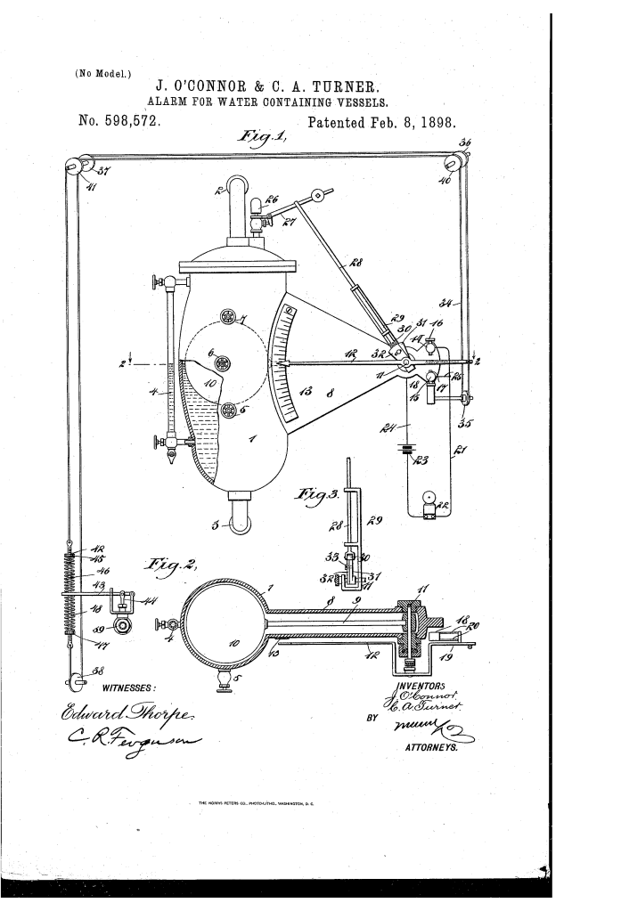
U.S. Patent No. 598,572, granted on February 8, 1898, to John O’Connor and Collatinus A. Turner of New York, N.Y., details an integrated monitoring, alarm, and water-level control apparatus designed primarily for steam boilers.
During the late 19th century, boiler explosions caused by low water levels were a persistent industrial hazard, while overfilling risked carrying water over into steam engine cylinders. O’Connor and Turner addressed these operational risks by engineering an inexpensive, durable, and positive-action mechanism that coupled visual measurement, multi-stage alarms (both electrical and acoustic), and automated feed-control directly to the vessel’s internal water level.
The Core Design: The Exterior Float-Lever Mechanism
The system relies on a secondary water cylinder 1 connected directly to the upper and lower sections of a steam boiler via pipes 2 and 3, ensuring identical water levels through hydrostatic equilibrium. Rather than confining complex linkages inside the pressure vessel, the inventors routed motion through an exterior housing.
- The Float and Sealed Rocker ShaftInside cylinder 1, a buoyant float 10 rides on the surface of the water.Float stem 9 passes through an adjoining casing 8 and connects rigidly to a transverse shaft 11.As the water level fluctuates, the float pivots shaft 11, translating vertical movement inside the pressurized cylinder into mechanical rotation outside the vessel.
- Visual and Electrical MonitoringShaft 11 extends outside casing 8 to drive pointer 12 across a graduated gage-plate 13, offering a mechanical backup should visual water-gage 4 become cloudy, broken, or inoperative.An arm 19 extending from pointer 12 carries contact-plate 18, which is mounted on flexible spring-wires 20.Upper and lower adjustable contact screws 16 and 17 are wired into an electrical circuit containing battery 23 and alarm bell 22.
Multi-Tiered Alarm & Control Sequence
The apparatus functions across distinct operational stages to warn operators and physically correct water levels:
| Step | Action | Functional Purpose |
| 1. Normal Tracking | Float 10 moves within set bounds; pointer 12 moves across gage-plate 13. | Provides continuous local monitoring of water height. |
| 2. Low Water Trigger | Float drops; contact-plate 18 hits screw 17; roller 30 slips off plates 31 and 32. | Closes electrical circuit to ring bell 22; drops lever 27 to blow steam-whistle 26. |
| 3. Valve Opening | Pointer extension 19 pulls cable 34; spring 46 yields against lever 43. | Opens feed-valve 39 to admit water under pressure or activate a steam feed-pump. |
| 4. High Water Shutoff | Float rises to maximum; plate 18 hits screw 16; cable pulls opposite run. | Sounds high-level alarm; forces lever 43 downward to close valve 39. |
Key Mechanical & Electrical Components
- Resilient Spring Mounting (20): Mounts contact-plate 18 on compliant spring-wires, allowing float 10 to continue moving after electrical contact is established so the cable linkage can fully cycle the valve without binding or damaging electrical terminals.
- Dual Acoustic Alarm System: Combines battery-powered bell 22 with steam-whistle 26. The whistle triggers when shaft-mounted supporting plates 31 and 32 rotate out from under push-rod roller 30, dropping lever 27. This provides an audible warning even if an engineer is far from the machine floor where an electric bell cannot be heard.
- Yielding Valve Linkage: Rod 42 passes loosely through valve-lever 43 and is capped by threaded collars 45 and 47 and springs 46. This compliant interface prevents float jamming if valve 39 sticks, ensuring emergency alarms still fire reliably.
- Adjustable Plates (31, 32): Connected to shaft 11 and locked relative to each other via set-bolt 33. Shifting their relative overlap adjusts the exact low-water drop threshold required to unseat roller 30 and sound whistle 26.
Industrial Impact
Operating steam plants at the turn of the 20th century required constant manual oversight to prevent catastrophic dry-firing and boiler breaches. O’Connor and Turner’s patent introduced several practical advances:
- Fail-Safe Redundancy: By integrating local visual indicators, remote battery-powered electrical bells, and vessel-powered steam whistles, the design eliminated single points of failure in low-water warning systems.
- Integrated Automation: It removed the time delay between alarm detection and operator intervention by mechanically coupling the float directly to the boiler feed valve or steam pump.
- Mechanical Tolerance: The incorporation of slotted plates, adjustable stops, and spring-loaded over-travel buffers allowed the unit to be retrofitted to varied boiler pressures and water chemistries without delicate calibration.
Summary of Claims
The patent explicitly claims:
- An alarm apparatus combining an external casing, an internal float, an exterior rocking shaft, an electric circuit, and an arm carrying a contact-plate to trigger high- and low-level electrical alarms.
- A mechanical cable-and-pulley connection between the rocker arm and a water-controlling valve, featuring a spring-yielding link to permit float movement regardless of valve resistance.
- An adjustable plate assembly (31, 32) mounted on the rocker shaft to support an actuating rod, engineered to release a weighted whistle valve lever when water drops past a designated limit.
- The application of a resilient spring-wire mounting for the electrical contact plate, permitting over-travel to coordinate electrical signaling with mechanical valve operation.
