
Alarm for Boilers (1896)
U.S. Patent No. 566,612, granted on August 25, 1896, to John O’Connor and Collatinus A. Turner, describes an automatic electromechanical monitoring system designed to sound an alert during extreme water-level fluctuations in steam boilers. O’Connor and Turner, inventors based in New York City, assigned partial rights to David D. Turner of Jersey City, New Jersey.
This invention solved a critical safety hazard in late 19th-century steam engine operations: detecting dangerous high or low water conditions that could lead to engine inefficiency, boiler rupture, or catastrophic explosion.
The Innovation: Adjustable Dual-Terminal Float Sensing
Traditional water-level indicators relied heavily on visual sight glasses or manual test cocks, which required constant operator monitoring. O’Connor and Turner introduced a self-contained, spring-loaded electrical contact mechanism driven directly by an internal float.
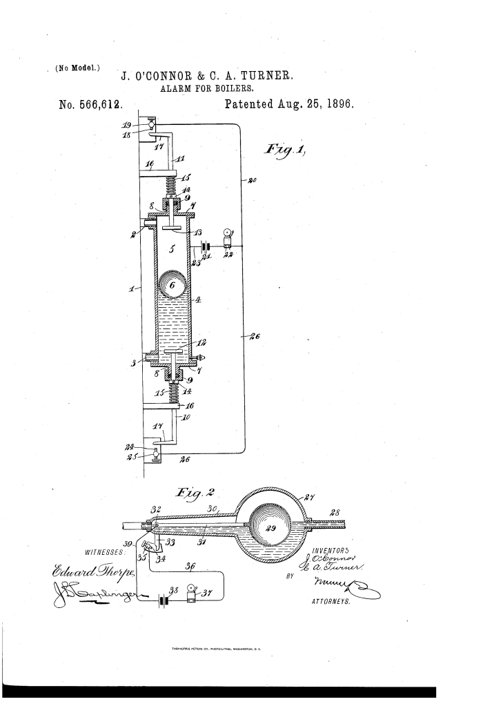
The key novelty of the primary design lies in its dual, spring-opposed sensing stems (10 and 11) and fully adjustable external contact stops. By sliding adjustable collars (14) along the stems, operators can calibrate the precise trigger thresholds for both high and low water conditions without dismantling the pressure vessel.
Key Features & Mechanics
- Continuous Monitoring: The vertical float chamber (4) communicates directly with the steam space (via pipe 2) and water space (via pipe 3) of the boiler, ensuring the internal float (6) mirrors the true water level.
- Sustained Alarm Signal: Contact screws (18 and 24) serve a dual purpose: completing the electrical circuit and physically arresting stem movement. This keeps the circuit closed so the alarm bell continues to ring as long as the dangerous water condition persists.
- Low-Friction Pressure Seals: Screwed stuffing boxes (9) maintain a tight steam and water seal where the stems exit the chamber while permitting free longitudinal motion.
Key System Components
The apparatus uses a combination of mechanical and electrical components to automate boiler safety monitoring:
| Component | Function |
| Float Chamber / Cylinder (4) | A pressure-tight enclosure connected above and below the water line to house the internal float. |
| Ball-Float (6) | A buoyant sphere that rises and falls with fluctuations in the boiler water level. |
| Stems & Enlarged Heads (10, 11, 12, 13) | Upper and lower sliding rods whose interior heads are physically engaged by the float at critical limits. |
| Adjusting Collars & Springs (14, 15) | Mechanical stops and return springs that maintain stem position and allow custom threshold calibration. |
| Contact Screws & Posts (18, 19, 24, 25) | Adjustable electrical terminals that complete the circuit and act as physical stops for the stem arms (17). |
| Electrical Circuit (20, 21, 22, 23, 26) | A wiring network powered by a battery (21) to actuate an alarm bell (22) when contacts close. |
How the Apparatus Functions
The primary embodiment operates through a clear mechanical-to-electrical sequence:
- Normal Operation: The ball-float (6) suspends freely between the upper head (13) and lower head (12). Springs (15) keep both stems held inward, holding the external lateral arms (17) away from the contact screws.
- Low-Water Trigger: As the water level drops, the float (6) settles onto the lower head (12). The weight of the float forces the lower stem (10) downward against its spring (15).
- Alarm Activation: The lower arm (17) strikes the adjustable screw (24), completing the electric circuit through wires (23 and 26) to sound the alarm bell (22).
- High-Water Trigger: Conversely, rising water forces the float (6) against the upper head (13), pushing stem (11) upward until its arm (17) strikes upper contact screw (18) to close the circuit via wire (20).
Alternative Embodiment: Pivoted Single-Float System
The patent also detail a simplified modification (Figure 2) for low-water monitoring:
- Structure: Uses a globular chamber (27) connected to the boiler water level via a single pipe (28).
- Action: A ball-float (29) rests on an internal lever arm (31) pivoted on a shaft (32).
- Actuation: As water drops, the falling float swings an external depending arm (33) against an adjustable contact screw (34), completing the circuit to battery (38) and bell (37) via wires (36 and 39).
Historical Impact
O’Connor and Turner’s alarm system reflects the rapid transition toward industrial automation and electromechanical safety controls in late Victorian-era manufacturing and marine transport.
- Improved Reliability: By placing mechanical springs and adjustable contact points outside the main pressure chamber, the design protected critical electrical contacts from direct exposure to corrosive steam and water scale.
- Versatility: The simple threaded collar adjustments allowed firemen and engineers to adapt the system to boilers of varying sizes, working pressures, and liquid thresholds.
- Enhanced Operational Safety: Automating continuous high/low warnings significantly reduced human error, mitigating low-water boiler explosions—one of the most destructive and common industrial hazard types of the 19th century.
About the Inventors
John O’Connor and Collatinus A. Turner were inventors based in New York City during the post-Civil War industrial boom. Operating out of the nation’s premier port and manufacturing hub, their work focused on practical electromechanical solutions for boiler room infrastructure, steam navigation, and municipal power systems.
Summary of Claims
The patent explicitly claims:
- An alarm apparatus featuring a float chamber, a float, an externally extending rod actuated by the float, a battery-powered bell circuit, and an adjustable contact-screw that acts as both circuit terminal and physical stop.
- A dual-stem configuration extending through the top and bottom of a float chamber, using internal float engagement and external return springs to complete an electrical alarm circuit at upper and lower thresholds.
- The combination of adjustable collars mounted on upper and lower stems, allowing operators to longitudinally calibrate the internal projection of the stems to customize the alarm trigger levels.
