
✈️ Airplane Appliance (Richard E. S. Toomey & James C. Evans, No. 1,749,858)
The patent by Richard E. S. Toomey and James C. Evans of Miami, Florida, describes an Airplane Appliance (Patent No. 1,749,858, 1930). This invention is a thermal anti-icing system designed to prevent the accumulation of sleet, snow, and ice on the wings of an aircraft. Toomey and Evans’s primary objective was to eliminate one of the most significant dangers of early aviation: the “freezing” of moisture on wing surfaces, which increases weight, alters aerodynamics, and can make a plane impossible to manage. Their innovation features a dual-chambered heat distribution system that repurposes hot exhaust gases from the engine to heat the wing’s leading edge.
Inventor Background: James C. Evans
James C. Evans (1900–1988) was a distinguished African American engineer, educator, and administrator. A graduate of MIT, Evans was a professor at West Virginia State College and later served as a high-ranking civilian official in the Department of Defense, where he played a key role in the integration of the U.S. Armed Forces. His 1930 patent, co-developed with Richard E. S. Toomey, demonstrates a sophisticated mastery of thermodynamics and aeronautical safety. At a time when flight was still in its “Golden Age” of experimentation, Evans applied rigorous engineering principles to solve the critical problem of atmospheric icing.
Key Mechanical & Thermal Systems
The device acts as a “thermal shield” for the wing, utilizing waste heat from the engine to maintain surface temperatures above freezing.
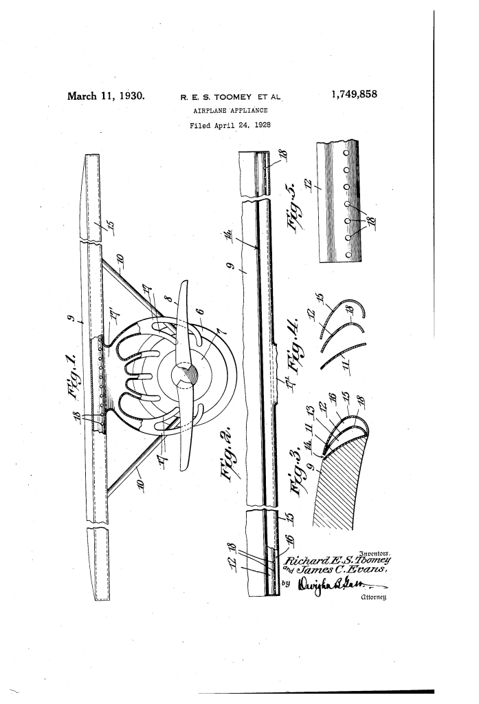
1. The Multi-Chambered Leading Edge (11, 12, 13, 15, 16)
- Protective Member (11): A metal guard is fitted to the forward edge of the wing (9).
- Plate (12) and Shell (15): Two concave metal plates are secured to the guard, creating two separate internal zones.
- Compartment (16): The forward-most space, which receives the initial blast of heat.
- Heat Chamber (13): The secondary space located behind the plate (12).
- Function: This nested construction prevents the “excessive or burning heat” of raw exhaust from damaging the wing structure. The shell (15) acts as a primary buffer, distributing heat before it reaches the wing’s main surface.
2. Exhaust Gas Distribution (17, 18)
- Inlet Pipes (17): Hot exhaust gases are led from the motor (7) through a manifold to the compartment (16).
- Distribution Openings (18): A series of holes in the internal plate (12) allow the gases to move from the forward compartment into the heat chamber (13).
- Action: This ensures that the heat is “evenly distributed” across the entire length of the wing rather than being concentrated in one spot near the engine.
3. The Restricted Discharge Neck (14) (Key Innovation)
- Design: The heat chamber terminates in a narrow discharge opening (14) at the upper forward edge of the wing.
- Induced Draft: As the airplane flies, the rapid passage of air over the wing creates a low-pressure zone at the neck.
- Function: This creates an induced draft, effectively “sucking” the hot gases out of the chamber and spreading them in a thin film over the upper surface of the wing. This provides a continuous thermal barrier that prevents moisture from freezing upon contact.
4. Dual Function: Muffler and Heater
- Acoustic Benefit: Because the exhaust gases must travel through a complex series of chambers and pipes before reaching the atmosphere, the device also functions as a muffler.
- Function: It reduces the deafening noise of the engine explosions, improving the pilot’s environment while simultaneously providing a critical safety function.
Improvements Over Standard Aircraft Wings
| Feature | Standard 1920s Wings | Evans’s Airplane Appliance |
| Icing Safety | Extremely vulnerable to sleet/snow. | Thermal anti-icing prevents ice from forming. |
| Weight Management | Ice buildup added hundreds of pounds. | Minimal added weight; uses thin metal plates. |
| Energy Efficiency | Exhaust heat was wasted. | Repurposes waste heat for safety. |
| Aerodynamics | Frozen moisture ruined lift profiles. | Maintains smooth wing surface in all weather. |
Significance to Aeronautical Engineering
James C. Evans’s anti-icing appliance influenced the development of bleed-air systems and all-weather aviation technology.
- The Foundations of Bleed-Air Anti-Icing: The logic of using hot engine gases to heat the wing’s leading edge is exactly how modern jetliners prevent icing today (using “bleed air” from the engines). Evans was a pioneer of this fundamental safety principle.
- Heat Shielding Technology: By using a dual-chambered system to prevent “burning” the wing, he anticipated the thermal management solutions required for high-speed flight.
- Integration of Safety and Utility: Combining a muffler with an anti-icing system demonstrated an early commitment to multi-functional component design, a core tenet of efficient aerospace engineering.
- Legacy of Excellence: As a Black engineer during the Jim Crow era, Evans’s work at the highest levels of technical and administrative service helped pave the way for the desegregation of the defense industry and the rise of future generations of Black aerospace professionals.
