

Air Pollution Control Device (1970)
U.S. Patent No. 3,520,113, granted on July 14, 1970, to Rufus Stokes, describes an exhaust purification and scrubbing apparatus designed to extract particulate matter, noxious gases, chemicals, and industrial odors before emissions enter the atmosphere.
This invention tackled a major industrial hazard: emissions from metal smelting and reclamation facilities, where burning extraneous coatings like rubber insulation off scrap lead and zinc released dense smoke and toxic pollutants. At the time, existing technologies—including cyclone filters, baghouses, and electrostatic precipitators—consistently clogged or failed to eliminate gaseous contaminants and fine soot. Stokes designed a compact, multi-stage wet-scrubbing system that utilized pressurized water submersion, spray filtration, and differential pressure absorption to clean exhaust streams.
The Innovation: Pressurized Multi-Chamber Wet Scrubbing
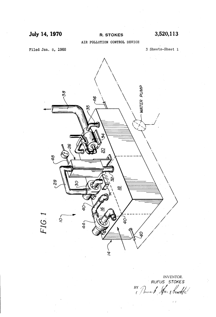
Standard wet scrubbers simply sprayed water over rising chimney smoke. Stokes engineered a sequential, closed hydrodynamic process within a multi-compartment tank (14) where exhaust gases are submerged, scrubbed, filtered, and subjected to pressure manipulation across three interconnected zones.
Why Multi-Chamber Pressure Scrubbing? Submerged Scouring: Forcing gas underwater breaks up large particulate agglomerations through high-shear hydraulic agitation. Pressure-Induced Absorption: Building backpressure above the water level forces fumes to remain submerged longer, dissolving soluble gases like sulfur dioxide that would otherwise escape. Quiescent Settling: A large, calm water volume gives remaining micro-particles adequate residence time to fall out of suspension prior to final release.
Key Technical Components
| Component | Function |
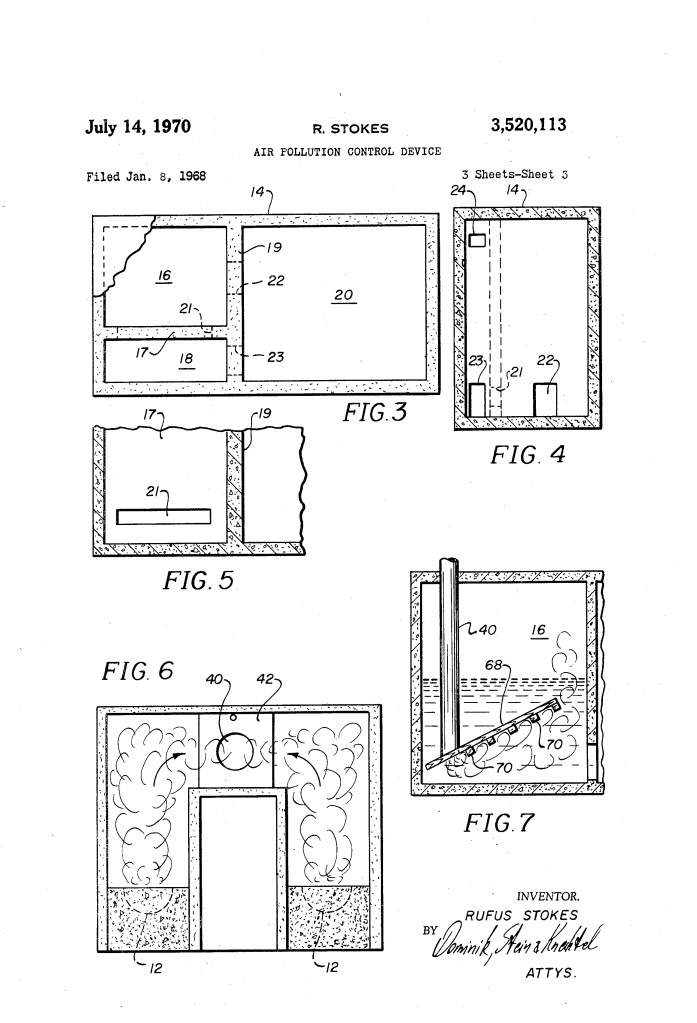
| Primary Mixing Chamber (16) | A water-filled vessel receiving raw industrial exhaust submerged beneath the waterline, initiating hydraulic agitation and particle fallout. |
| Submerged Manifold (68) | An upwardly angled terminal pipe fitted with spaced discharge ports (70) to maximize contact area between bubbles and water. |
| Precipitator-Filter Unit (26) | An overhead chamber equipped with water spray jets (27) to form a dense mist that agglomerates fine aerosols into droplets, coupled with mechanical filters (29). |
| Secondary Mixing Chamber (18) | A pressurized scrubbing zone where restricted exhaust passage impedes gas escape, maximizing liquid absorption of acidic gases. |
| Settling Chamber (20) | A large, quiescent water reservoir that provides extended dwell time for fine suspended matter to settle out while cooling and diluting recirculated acidic water. |
| Afterburner (34) | A thermal combustion unit located before the exhaust stack (38) to incinerate residual combustible vapors and sulfides under heavy operating loads. |
How the Apparatus Functions
| Step | Action | Functional Purpose |
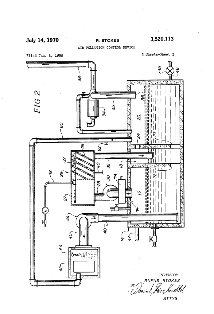
| 1. Primary Submersion | High-pressure blowers (44) pull exhaust from the collection hood (42) and inject it beneath the water surface via the ported manifold (68). | Creates vigorous bubbling and hydraulic scouring to trap heavy soot and absorb water-soluble chemicals. |
| 2. Mist Agglomeration & Filtration | Overhead blowers (30) draw the scrubbed gas into the precipitator-filter unit (26), driving it through continuous water mist sprays (27) and physical filters (29). | Converts fine airborne dust into heavy droplets and captures residual particles that bypassed the primary tank. |
| 3. High-Pressure Absorption | The washed gas is blown into the secondary chamber (18). The small outlet window (24) restricts exit flow, generating sustained backpressure above the water line. | Keeps gases trapped under pressure at the water interface, driving noxious gases like sulfur dioxide into solution. |
| 4. Quiescent Settling & Discharge | Fumes pass through the window (24) into the expansive settling chamber (20) before rising through natural chimney draft (38). | Lowers gas velocity, letting remaining airborne dust fall out into the calm water reservoir before clean air exits. |
Performance: Prototype Test Results
Stokes submitted comprehensive gas chromatograph and mass spectrometer data analyzing gas samples collected from burning bunker oil, raw sulfur, and rubber-coated electrical cable:
Hydrocarbon Elimination: Bunker Oil Emissions: Concentrations of methane (57 ppm), ethylene (30 ppm), and propylene (40 ppm) were reduced to 0 ppm—achieving a 100 percent removal rate.
Rubber Cable & Sulfur Combustion:
| Contaminant | Concentration Before | Concentration After | Overall Removal |
| Methane | 57 ppm | 0 ppm | 100.00% |
| Ethylene | 30 ppm | 0 ppm | 100.00% |
| Propylene | 40 ppm | 0 ppm | 100.00% |
| Carbon Disulfide | 15 ppm | 3 ppm | 80.00% |
| Acetylene | 58 ppm | 14 ppm | 75.86% |
| Sulfur Dioxide | 47,000 ppm (4.7%) | 20,000 ppm (2.0%) | 57.44% |
| Hydrogen Sulfide | 160 ppm | 72 ppm | 55.00% |
| Carbonyl Sulfide | 66 ppm | 31 ppm | 53.03% |
Operational Maintenance and Circulation
To manage continuous industrial operation, the system incorporates automated fluid and pressure controls: Continuous Water Circulation: A water pump (45) continuously pulls liquid out of the secondary chamber (18) and cycles it into the larger settling chamber (20). This counteracts localized acid accumulation and heat buildup. Reservoir Dilution & Neutralization: The settling chamber acts as a dilution reservoir to prevent saturation; basic reagents can be added directly to neutralize acidic buildup and maintain a neutral pH. Pressure Relief Loop: An adjustable bypass line (60) with a relief valve (62) returns excess fumes from the settling chamber back to the inlet hood (42) if pressure exceeds operational limits, preventing process disruption.
About the Inventor: Rufus Stokes
Rufus Stokes was an African American inventor born in Alabama who later worked in Chicago, Illinois. Patents: Stokes held several patents in environmental remediation, incinerator design, and exhaust scrubbing, most notably his pioneering 1968 and 1970 filings for industrial emissions filtration. Impact: His compact, versatile emissions-control designs challenged the conventional belief that industrial wet scrubbers had to be massive, cost-prohibitive installations, demonstrating that multi-phase scrubbing could be adapted directly to municipal incinerators, smelters, and industrial boilers. Legacy: Stokes’s work predated the widespread federal enforcement that followed the passage of the Clean Air Act of 1970, anticipating the need for scalable emissions abatement in heavily populated urban and industrial zones.
Summary of Claims
The patent explicitly claims: An air pollution control apparatus containing a primary mixing chamber, secondary mixing chamber, and settling chamber, all partially filled with continuously circulated water. Submerged gas delivery mechanisms driven by blowers that force raw fumes underneath the liquid line for initial scouring. A secondary chamber structurally proportioned with restricted egress to create internal pressure, preventing premature gas release and forcing gas absorption into the water. An auxiliary precipitator-filter subsystem positioned between stages, featuring dedicated water mist nozzles and mechanical particulate filters. A pressure-relief bypass loop equipped with a regulator valve to vent and re-route excess pressure back into the intake hood.
