
Adjustable Shackle (1969)
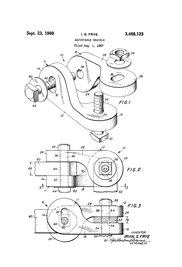
U.S. Patent No. 3,468,123, granted on September 23, 1969, to Irvin S. Frye (assigned to Ocean Science & Engineering, Inc.), provides an adaptable, heavy-duty mechanical connector designed to couple apertured structural elements—such as eyebolts, mooring eyes, plates, and chains—of differing widths and thicknesses without requiring shims, spacers, or specialized custom fittings.
This invention resolved an enduring problem in marine, rigging, and mechanical operations: conventional shackles and clevises have fixed jaw dimensions. When coupling mismatched hardware or connecting two elements of unequal thickness, riggers traditionally had to stack loose shims or fabricate custom spacers to eliminate lateral play, introducing structural vulnerabilities, corrosion traps, and assembly delays. Frye engineered a pair of complementary, dual-eared link castings with orthogonal geometry and slotted bolt holes that allow both clamping ends to adjust independently.
The Core Design: The Orthogonal Dual-Link System
The connector achieves independent two-dimensional adjustment through a complementary pair of rigid links, each featuring two integral ears oriented at right angles (normal) to each other.
- Angular Offset Ears (14, 16 and 24, 26)
- First Link (11): Features a first ear (14) at one end and a longitudinally displaced second ear (16) at the opposite end, extending normal (90 degrees) to the plane of the first ear.
- Second Link (12): Features a third ear (24) and a fourth ear (26) with the exact same longitudinal spacing and 90-degree angular offset.
- Parallel Opposing Jaws: When the two links are placed together, ear 14 opposes ear 24 to form a first clamping jaw, while ear 16 opposes ear 26 to form a second clamping jaw oriented at 90 degrees to the first.
- Orthogonal Elongated Slots (32, 38)
- Slotted Ear (14): Ear 14 contains an elongated slotted aperture (32), while opposing ear 24 contains a round circular hole (36).
- Slotted Ear (26): Ear 26 contains an elongated slotted aperture (38), while opposing ear 16 contains a round circular hole (34).
- Independent Clamping: Because slot 32 is elongated parallel to the clamping plane of ears 16 and 26, and slot 38 is elongated normal to that direction (parallel to ears 14 and 24), clamping down on one member does not pinch, bind, or misalign the bolt passing through the other member. Each jaw adjusts its gap independently to lock securely onto unequal thicknesses.
How the Apparatus Functions
Assembly follows a direct mechanical progression to secure two members of disparate sizes:
| Step | Action | Functional Purpose |
| 1. First Member Insertion | First member (60) is positioned between opposing ears (14, 24). | Aligns member opening (64) with slotted aperture (32) and round opening (36). |
| 2. Primary Clamping | Bolt (40) is passed through openings (32, 64, 36) and tightened with nut (46). | Draws ears (14, 24) flush against member (60) across thickness (66) without bending the links. |
| 3. Second Member Insertion | Second member (62) is positioned between opposing ears (16, 26). | Aligns member opening (74) with round opening (34) and slotted aperture (38). |
| 4. Secondary Clamping | Bolt (42) is passed through openings (34, 74, 38) and tightened with nut (56). | Draws ears (16, 26) flush against member (62) across thickness (76), sliding along slot (38) without disturbing the first connection. |
Key Mechanical Components
| Component | Function |
| First Link (11) | One-piece cast rigid body comprising intermediate portion (18), slotted first ear (14), and round-apertured second ear (16). |
| Second Link (12) | One-piece cast rigid body comprising intermediate portion (28), round-apertured third ear (24), and slotted fourth ear (26). |
| First Clamping Assembly (40, 46) | Threaded bolt with head (43) and mating nut (48) extending through ears (14, 24) to lock first member (60). |
| Second Clamping Assembly (42, 56) | Threaded bolt with head (53) and mating nut (58) extending through ears (16, 26) to lock second member (62). |
| Washers / Lock Washers | Placed under bolt heads and nuts to distribute bearing loads and prevent loosening under vibration. |
| Annular Bearings (Optional) | Positioned around the bolts between the ears and members when free rotation or pivoting linkage is required instead of a rigid clamp. |
Historical and Technical Impact
Irvin S. Frye’s connector provided practical operational and economic advantages across marine engineering and heavy industrial rigging:
- Elimination of Loose Shims: Precludes the need to carry, size, or stack shims when joining hardware of disparate dimensions, preventing play and vibration wear.
- Simple Casting Economy: Both links (11, 12) are robust, one-piece castings requiring minimal machining beyond drilling and slotting, while utilizing standard off-the-shelf threaded fasteners.
- Universal Coupling Versatility: Accommodates irregular hardware pairings—such as securing a thin structural gusset plate directly to a thick cast mooring eye—while supporting either rigid lockup or free rotational articulation via sleeve/annular bearings.
About the Assignee: Ocean Science & Engineering, Inc.
Ocean Science & Engineering, Inc. (OSE), based in Washington, D.C., was a pioneering ocean engineering firm founded in the 1960s by Willard Bascom and colleagues from the historic Mohole Project.
- Marine Engineering Frontiers: OSE designed specialized deep-ocean exploration systems, subsea drilling equipment, mineral recovery vessels, and specialized mooring hardware for extreme offshore environments.
- Rigging Innovation: In offshore and marine towing operations, connecting cables, chains, buoys, and winches of non-standardized gauges presented persistent field hazards. Frye’s shackle provided OSE’s field crews and maritime operators with a universal, high-strength rigging link capable of handling rapid offshore connections without downtime.
Summary of Claims
The patent explicitly claims:
- A shackle comprising a first elongated link having two longitudinally displaced, angularly disposed ears, and a second elongated link having matching displaced, angularly disposed ears.
- Clamping means configured to draw the first and third ears together to hold a first member, and a second clamping means to draw the second and fourth ears together to hold a second member.
- Connector configurations where at least one ear aperture is elongated into a slot.
- A linkage wherein the aperture of the first ear is elongated parallel to the plane of the second and fourth ears, and the aperture of the fourth ear is elongated in a direction normal to the elongation of the first ear.
