
Rotary Engine (1892)
U.S. Patent No. 478,271, granted on July 5, 1892, to Andrew Beard, describes a highly balanced and easily reversible rotary steam engine designed to eliminate lateral shaft wear. Andrew Beard, an acclaimed inventor based in Woodlawn, Alabama, was a former railroad worker whose mechanical breakthroughs greatly improved industrial efficiency and transport safety.
This specific invention solved a persistent problem in early rotary engine designs: unequal lateral steam pressure that forced driving shafts out of alignment, causing severe friction, bearing failure, and uneven wear.
The Innovation: Concentric Annular Walls and Inner Steam Intake
Traditional rotary engines took steam on the outside of the piston head, pushing the entire assembly violently to one side of the bearing. Beard’s breakthrough was a balanced internal design that distributes steam pressure symmetrically.
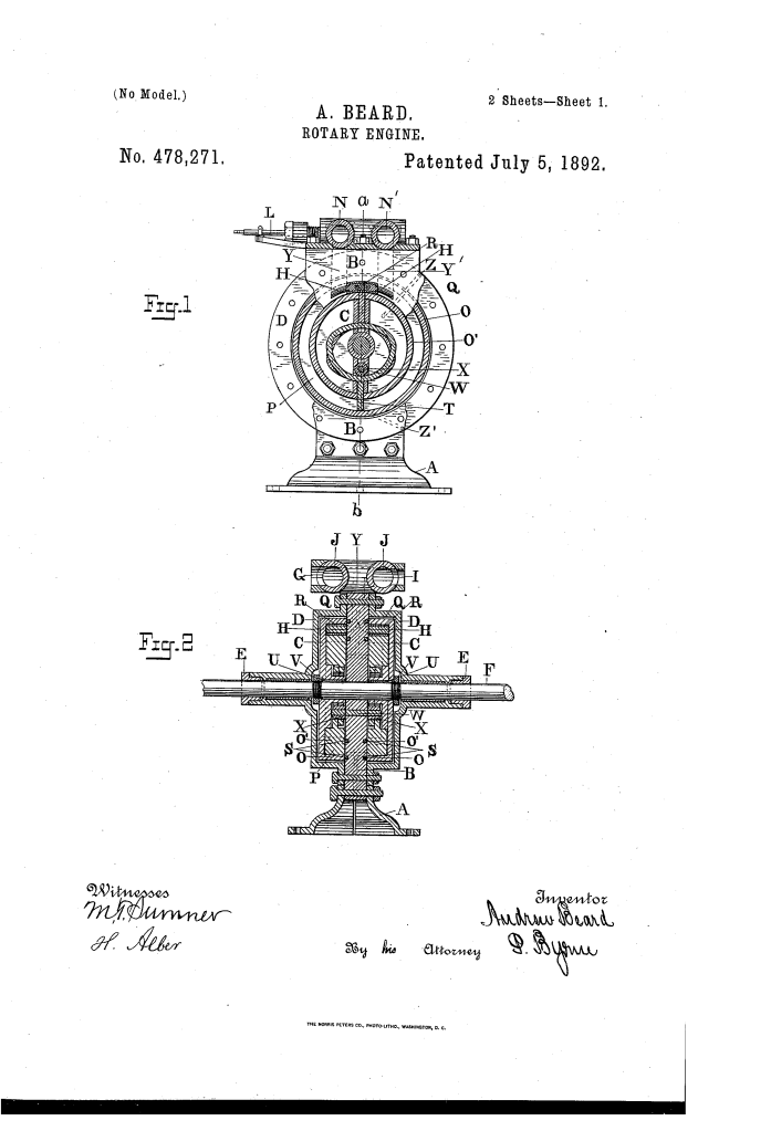
Instead of utilizing a single solid rotor, each cylinder head (C) features two concentric rings: an outer annular wall (O) and an inner annular wall (O1), creating an enclosed annular steam space (P) between them.
Why the Inner Steam Space?
- Perfect Balance: Steam is admitted directly into the internal channel between the walls through ports (H). Because the steam expands outward equally in all radial directions from the center, the running parts remain perfectly balanced, protecting the main driving shaft (F) from lateral displacement.
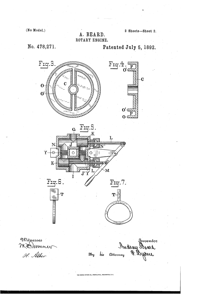
- Continuous Rotation: Each head is fitted with two reciprocating pistons (T). By utilizing a dual-head layout separated by a central partition, at least one piston is always fully extended to catch the steam, ensuring unbroken, fluid rotational power.
Key Mechanical Components
The engine is a synchronized assembly where every component works to maintain a flawless steam seal and smooth rotation:
| Component | Function |
| Central Partition (B) | The structural core dividing the engine into two halves. It houses the oil channels, steam passages (Y, Y1), and fixed cam studs. |
| Reciprocating Pistons (T) | Mounted in slots within the rotating heads. They feature specialized cam-loops on their inner ends that ride over fixed rollers (X). |
| Steam Abutments (Q) | Stationary blocks secured to the central partition that block the annular space, forcing the expanding steam to push against the movable pistons instead of bypassing them. |
| Spring-Loaded Packing (R, I) | Metallic strips under the abutments and concentric packing rings in the partition, both backed by tiny springs to maintain an absolute steam-tight joint without binding. |
| Recessed Outer Casings (D) | Exterior protective covers bolted to the central partition. Crucially, they are recessed so they never physically touch the spinning piston heads, eliminating housing friction. |
How the Apparatus Functions
The operational cycle relies on mechanical cams to manipulate the pistons and dual plungers to dictate direction:
1. Driving the Rotation
Steam enters through the vertical passages and passes into the annular space (P). The fixed rollers (X) force the cam-looped pistons to fully extend against the outer wall (O) on the lower half of their revolution. The steam traps itself between the stationary abutment (Q) and the extended piston, forcing the head and main shaft to rotate.
2. The Cam Clearance
On the upper half of the revolution, the track of the cam-loop draws the piston inward toward the shaft. This retracts the piston completely away from the outer wall, allowing dead exhaust steam to escape through the return ports and letting the piston smoothly glide past the fixed steam abutments without colliding.
3. Reversing and Control
A top-mounted steam chest houses a valve mechanism featuring two plungers (K) operated by a single hand-lever (M):
- Forward/Reverse: Shifting the hand-lever moves the plungers to opposite ends of the valve cylinder. This reverses the roles of the steam lines—the intake passages instantly become the exhaust lines, and the exhaust lines become the intake, immediately spinning the engine backward.
- Neutral Cut-Off: Placing the hand-lever precisely in the center aligns the plungers to block both passages simultaneously, completely cutting off the steam supply to stop the engine.
About the Inventor: Andrew Beard
Andrew Jackson Beard was one of the most remarkable southern inventors of the post-Reconstruction era, rising from structural adversity to achieve profound engineering success.
- Patents: He held multiple landmark patents, including an automatic plow design and a revolutionary rotary steam engine model. His most famous invention was the “Jenny Coupler” (1897), an automatic railroad car coupler that saved countless trainmen from losing limbs or lives.
- Impact: Before Beard’s balanced rotary design, high-speed rotary engines wore out their bearings rapidly due to asymmetric pressure. His concentric wall design allowed small-scale engines to run cheaply and smoothly with vastly reduced maintenance requirements.
- Legacy: Inducted posthumously into the National Inventors Hall of Fame, Beard proved that elite-level thermodynamic and mechanical design could be engineered independently through raw practical insight.
Summary of Claims
The patent explicitly claims:
- The combination of an engine base, a central partition, and recessed outer casings enclosing piston heads that utilize cam-loops riding over stationary rollers to reciprocate the pistons.
- A steam chest design incorporating a single reversing hand-lever and dual plungers working in tandem with symmetric downward steam passages.
- Stationary steam-tight abutments filling the internal annular spaces of the piston heads, positioned directly between the steam ports on both sides of a central dividing partition.
