
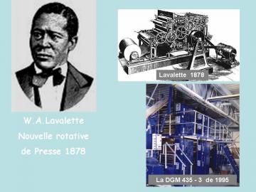
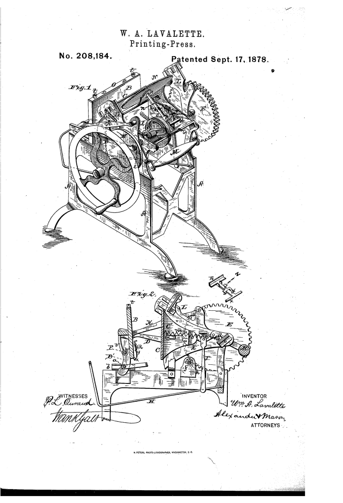
Improvement in Printing-Presses (William A. Lavalette, No. 208,184)
The patent by William A. Lavalette of Washington, D.C., describes certain Improvements in Printing-Presses (Patent No. 208,184, 1878). The invention focuses on refining the mechanism of a jobbing or platen press to ensure smooth operation, controlled inking, and precise, square contact between the platen and the bed.
Inventor Background: William A. Lavalette
William A. Lavalette was an inventor focused on machinery and mechanical efficiency. His invention addresses the mechanical challenges inherent in platen presses, where a flat printing surface (platen) must move rapidly toward a flat type surface (bed) to apply pressure. Achieving smooth motion and perfect parallelism was critical for high-quality printing.
Invention and Mechanism
The press features a unique combination of hinges, cams, and linkages to achieve precise motion control for the platen and includes several features for smooth operation and quick setup.
1. Platen Motion (Two-Part Movement) (Key Innovation)
The platen (B) movement is split into two synchronized actions:
- Rocking Motion (Opening/Closing): The platen is hinged to a sliding shaft (
). Pitmen (D) connected to crank pins (
) on drive disks (E) rock the platen forward from an open position to a perpendicular (vertical) position near the bed (G).
- Impression/Sliding Motion (Final Thrust): When the platen is vertical, a forked draw-rod (I), placed on the sliding shaft (
), is actuated by a cam-groove () on a cam disk (G).
- Function: This cam-action bodily moves the entire sliding shaft () and platen (B) forward, bringing the platen face “square against the bed” to make the final impression. It then immediately draws the platen back.
2. Bed Control (Safety and Adjustment)
- Toggle-Joint Retraction: The bed (G) is connected to a system of toggle-joints () linked by arms (J) to a lever or treadle (H).
- Function: Pressing the lever (H) breaks the toggles, drawing the bed back so that no impression will be taken when the platen comes up. This acts as an emergency trip or safety mechanism.
3. Smooth Operation and Counterbalancing
- Roller-Carrying Levers (L): The platen is connected to these levers, which carry rollers (inking rollers).
- Weight (M): A weight (M) is attached between the rear/lower ends of these levers (L).
- Function: This weight counterbalances the weight of the rollers, making the press run “more smooth and even, without the jar so often experienced.”
4. Inking and Tympan System
- Inking-Table (N): Attached to a shaft (
), which is rotated incrementally by a tooth or lug (
) on the cam-disk (G) engaging a pinion (
).
- Tympan Setup: A bar (
) at the top of the platen fastens the tympan’s upper edge. The lower end of the tympan is rolled upon a shaft (P) on the back of the platen, where a ratchet wheel (
) holds the tension. This allows the tympan to be easily loosened for paper removal.
Concepts Influenced by This Invention
Lavalette’s press influenced the design of subsequent printing, forming, and stamping machinery by pioneering precise, synchronized motion control to achieve high-force, parallel contact.
- Synchronized Multi-Motion Kinematics: The primary influence is the splitting of the platen’s movement into two precisely timed motions (rocking + sliding thrust). This sequential kinematic principle influenced the design of high-speed automated machinery where an object must be moved close to a target and then given a controlled, final, perpendicular force.
- Cam-Driven Final Thrust: The use of a cam and draw-rod (I) to provide the final, powerful, and parallel closing thrust is a foundational principle of all high-speed platen-style presses, stamping machines, and forming dies
. The cam ensures the impulse is rapid and that the contact faces remain parallel throughout the impression stroke.
- Operator-Controlled Safety Interlocks: The inclusion of the toggle-actuated bed retraction (H) influenced the design of safety trips and emergency stops in industrial machinery, allowing the operator to quickly disable the main function (impression) without stopping the entire machine drive.
- Counterbalanced Mechanisms: The use of a counterweight (M) attached to moving linkages to reduce vibration (“jar”) and ensure smooth operation is a fundamental principle in all high-speed reciprocating and oscillating industrial machinery.
